Auxiliary device and method for accurately adjusting and fixing engineering laser resonant cavity lens

An auxiliary device and precision adjustment technology, which is applied in the direction of lasers, laser components, phonon exciters, etc., can solve the problems of time-consuming and labor-intensive adjustments, and difficulties in precise adjustment of laser resonator lenses

Inactive Publication Date: 2018-08-31
HARBIN INST OF TECH
View PDF3 Cites 7 Cited by
  • Summary
  • Abstract
  • Description
  • Claims
  • Application Information

AI Technical Summary

Problems solved by technology

[0003] In order to solve the difficult and labor-intensive adjustment of laser resonator lenses currently used in engineering, the present invention provides a device and method for precise adjustment and fixing of engineering laser resonator lenses. while ensuring its high stability

Method used


Image

  • Auxiliary device and method for accurately adjusting and fixing engineering laser resonant cavity lens

Examples


specific Embodiment approach 1

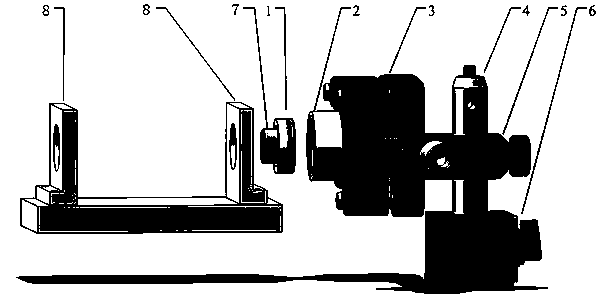
[0023] Specific Embodiment 1: This embodiment provides an auxiliary device for precise adjustment and fixing of engineering laser resonator mirrors. Since the laser resonator is usually composed of two mirrors, the above-mentioned precision adjustment and fixing assistance in actual operation The device needs two sets. Such as figure 1 As shown, each set of precision adjustment and fixing auxiliary devices is composed of a structural part 1 for installing a resonant cavity lens, a sleeve 2, an adjustment frame 3, an extension rod 4, a universal rod frame 5, and a magnetic base 6, wherein:

[0024] One end of the sleeve 2 is screwed to the structural member 1, and the other end is fixed on the adjustment frame 3;

[0025] The adjustment frame 3 is fixed on the universal rod frame 5;

[0026] The universal rod frame 5 is sleeved on the connecting rod 4;

[0027] The lower end of the connecting rod 4 is fixed on the magnetic base 6 .

[0028] In this embodiment, the structura...

specific Embodiment approach 2

[0034] Embodiment 2: This embodiment provides a method for using the precise adjustment and fixing device described in Embodiment 1 to realize the precise adjustment and fixing of engineering laser resonator mirrors. The method is implemented by the following steps:

[0035] Step 1, the resonant cavity lens 7 is cured and glued to the structural member 1 through ultraviolet glue;

[0036] Step 2. Assemble the magnetic base 6, the universal rod frame 5, the connecting rod 4 and the adjustment frame 3. The height and angle of the adjustment frame 3 can be adjusted;

[0037] Step 3: screw the structural part 1 and the sleeve 2 together through threads, and then fix the sleeve 2 on the adjustment frame 3, and the fixing between the two is completed by the top wire on the adjustment frame 3;

[0038] Step 4: Build the laser to be debugged used in the project, and fix the two resonant cavity frames 8 on which the resonant cavity lens 7 is installed to the laser base plate. The inner...


PUM


Abstract

The invention discloses an auxiliary device and method for accurately adjusting and fixing an engineering laser resonant cavity lens. The auxiliary device comprises a structural piece, a sleeve, an adjustment rack, a connection rod, an universal rod rack and a magnetic seat, wherein one end of the sleeve is in threaded connection with the structural piece, the other end of the sleeve is fixedly arranged on the adjustment rack, the adjustment rack is fixedly arranged on the universal rod rack, the universal rod rack sleeves the connection rod, and a lower end of the connection rod is fixedly arranged on the magnetic seat. The lens is cured and pasted onto the structural piece by ultraviolet glue, the accurate angle adjustment of the resonant cavity lens is achieved by the auxiliary device,so that optimal laser output is achieved; and finally, the auxiliary structural piece and a laser resonant cavity rack to be debugged are cured and pasted by the ultraviolet glue, the auxiliary deviceis removed, and the adjustment and fixing of the lens are completed. By the auxiliary device, the problem of difficulty in accurate adjustment of the laser resonant cavity lens is solved, and accurate adjustment and high stability of the resonant cavity lens are achieved.

Description

technical field [0001] The invention relates to an auxiliary device and method for precise adjustment and fixing of laser resonator mirrors used in engineering. Background technique [0002] For lasers built on experimental benches or commercial lasers, the two mirrors that constitute the resonator are usually installed on a conventional two-dimensional optical adjustment frame, and the optical adjustment frame is used to achieve precise adjustment of the resonator, so that the output performance of the laser is optimal. change. The advantage of this method is that the resonant cavity is easy to adjust, but the disadvantage is that the resonant cavity has poor stability. Under the action of shock vibration or high and low temperature, the laser is easily out of adjustment, resulting in a drop in output power. Lasers used in engineering or military use require that the laser can operate stably in extremely harsh environments such as vibration and temperature changes. The ord...

Claims


Application Information

Patent Timeline
Patent Type & Authority Applications(China)
IPC IPC(8): H01S3/105G02B27/62
Inventor 李旭东王佳闫仁鹏马欲飞樊荣伟董志伟陈德应
Owner HARBIN INST OF TECH
Why Eureka
Try Eureka