Composite processing device and composite processing method

A composite processing and processing area technology, which is applied in the direction of additive processing, metal processing equipment, metal processing machinery parts, etc., can solve the problem that the processing area cannot be visually confirmed, and achieve the effect of easy visual confirmation

Active Publication Date: 2019-11-22
YAMAZAKI MAZAK KK
View PDF9 Cites 0 Cited by
  • Summary
  • Abstract
  • Description
  • Claims
  • Application Information

AI Technical Summary

Problems solved by technology

[0005] When the shielding wall described in Patent Document 1 is directly applied to a combined machining device that performs two kinds of machining, such as cutting machining and machining using arc discharge, etc., in the same machining area, the operator cannot perform the cutting process due to the shielding wall. Visually confirm the status of the processing area

Method used


Image

  • Composite processing device and composite processing method
  • Composite processing device and composite processing method
  • Composite processing device and composite processing method

Examples


no. 1 approach >

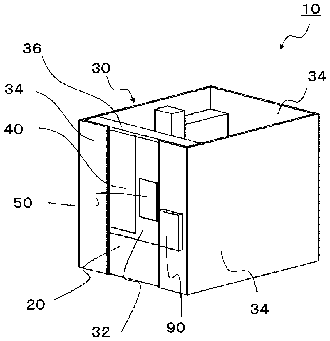
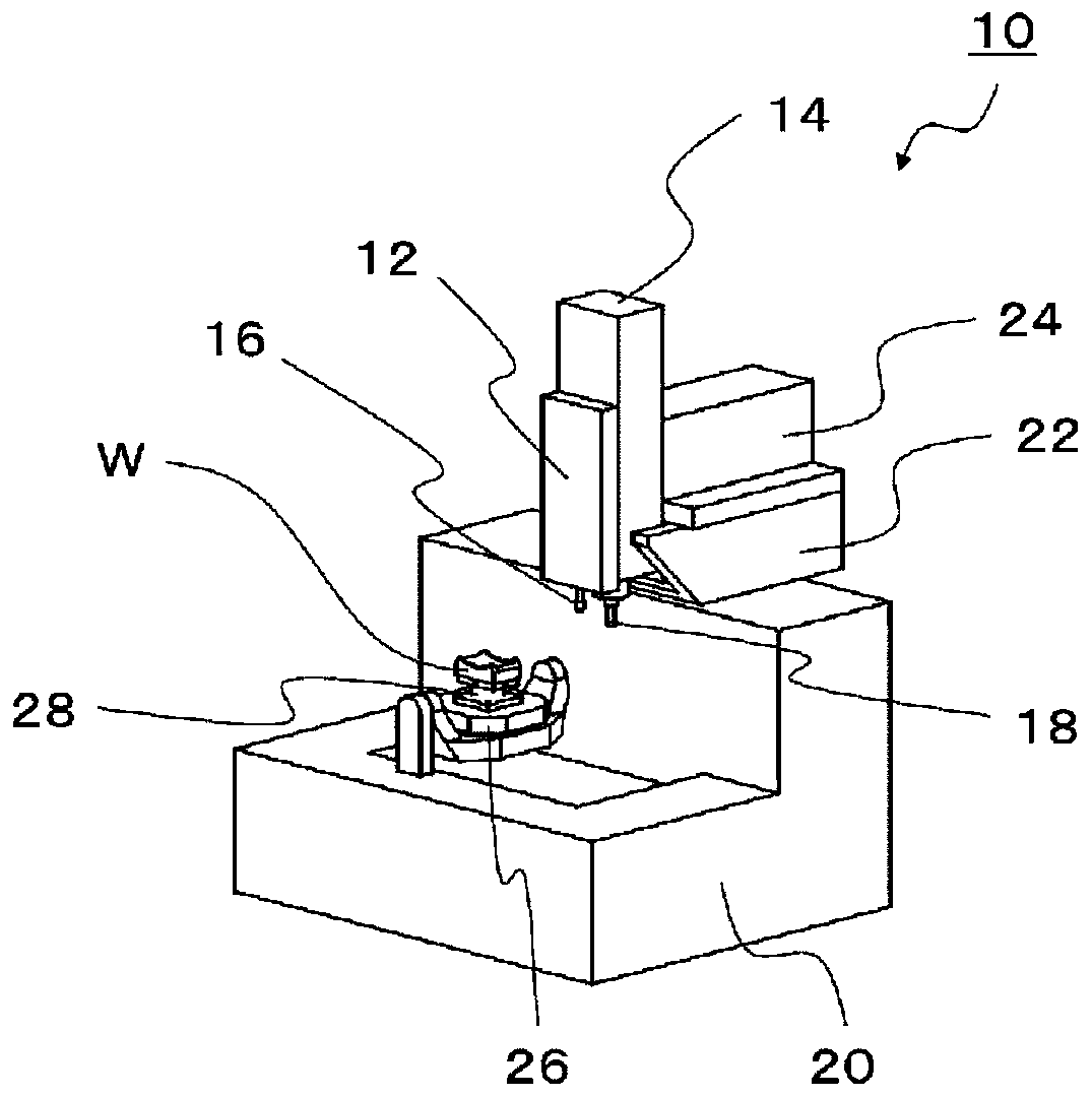
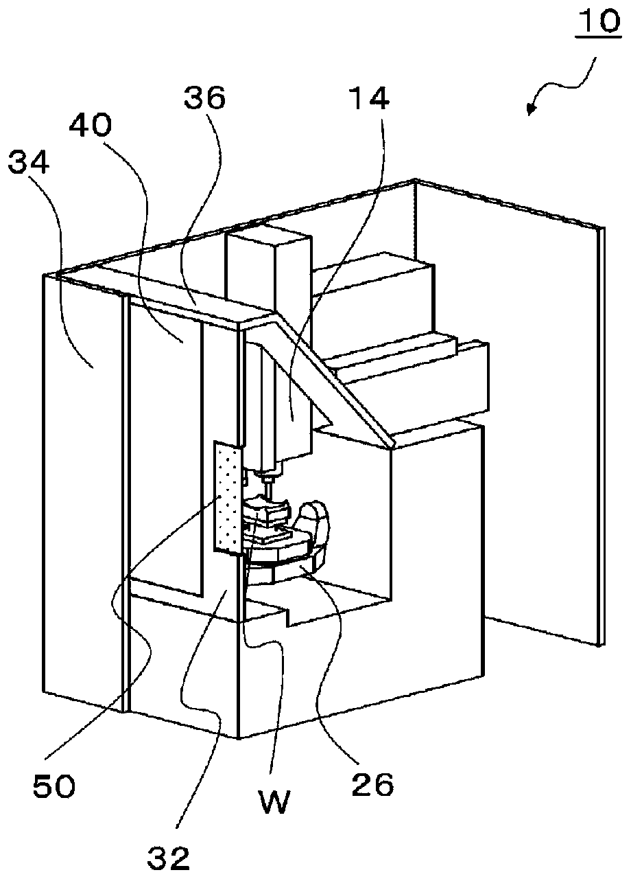
[0052] use figure 1 5 to 5 illustrate the combined processing device 10 according to the first embodiment of the present invention.

[0053] figure 1 is an external view of the combined processing device 10 of the first embodiment, figure 2It is a schematic diagram showing the interior of the composite processing device 10 without a cover. Such as figure 1 and figure 2 As shown, the composite processing device 10 according to the first embodiment of the present invention includes: an additive manufacturing unit 12, which irradiates energy on the workpiece W in the processing area to perform additive manufacturing; a cutting processing unit 14, which performs cutting processing on the workpiece W in the processing area. the cover part 30 covering the processing area; Here, the processing area refers to an area where additive manufacturing or cutting processing is performed on the workpiece W by the hybrid machining device 10 .

[0054] The cover part 30 includes: a door...

no. 2 approach >

[0073]A composite machining device 110 according to a second embodiment of the present invention will be described with reference to FIG. 6 . In the first embodiment, the light-shielding filter 50 is arranged on the front cover 32 fixed to the composite processing apparatus 10. As shown in FIG. In contrast, the second embodiment is different in that one light-shielding filter 150 is arranged on each of the door portions 140 arranged to be openable and closable.

[0074] In addition, the structure of the machine tool required for additive manufacturing or cutting processing itself is different from the figure 2 The structure described in the first embodiment shown is the same, and therefore description thereof will be omitted here.

[0075] FIG. 6 is a schematic diagram of a composite machining device 110 according to a second embodiment of the present invention. Figure 6A is an external view of the composite processing device 110 in a state where the door 140 is closed, ...

no. 3 approach >

[0087] A composite machining device 210 according to a third embodiment of the present invention will be described with reference to FIGS. 7 to 9 . In the second embodiment, one light-shielding filter 150 is disposed on each of the double-opening door portions 140 . In contrast, the third embodiment is different in that a plurality of light-shielding filters 250 are respectively arranged on the double-opening door portion 240 .

[0088] In addition, the structure of the machine tool required for additive manufacturing or cutting processing itself is different from the figure 2 The structure described in the first embodiment shown is the same, and therefore description thereof will be omitted here.

[0089] FIG. 7 is a schematic diagram of a composite machining device 210 according to a third embodiment of the present invention. Figure 7A is an external view of the composite processing device 210 in a state where the door 240 is closed, Figure 7B It is a three-dimensiona...


PUM


Abstract

The invention provides a composite processing device and a composite processing method. The compound processing device includes: an additive manufacturing part, which irradiates energy to the workpiece in the processing area to perform additive manufacturing; a cutting processing part, which cuts the workpiece in the processing area; a cover part, covering the processing area; The light-shielding filter is arranged on at least one surface of the cover portion, and changes the light-shielding degree according to the light received from the processing area.

Description

technical field [0001] The invention relates to a composite processing device and a composite processing method. Background technique [0002] At present, there is known a hybrid processing technology in which three-dimensional layered molding (hereinafter referred to as "additive manufacturing") is performed on a metal workpiece by welding or the like, and the formed object formed by the additive manufacturing is processed by cutting. etc. finishing. [0003] Here, a processing device that welds workpieces using arc discharge or laser has a light-shielding wall surface covering the surroundings in order to protect the operator from the light emitted from the irradiation unit during welding. Furthermore, there is a known processing device that provides a workpiece port for loading and unloading workpieces in a part of the light-shielding wall surface, and the port can be blocked by a shielding wall (for example, refer to Patent Document 1). [0004] Patent Document 1: Japa...

Claims


Application Information

Patent Timeline
Patent Type & Authority Patents(China)
IPC IPC(8): B23P23/04B22F3/16B23K9/32B22F3/105B23K26/21B23K26/34B23Q11/08B33Y30/00
CPCB22F3/162B23P23/04B33Y30/00B23Q11/0891B33Y40/00B33Y10/00B22F2003/247Y02P10/25B22F10/50B22F10/25B22F10/22B22F12/90B22F12/82B33Y50/02B22F3/24
Inventor 植村和树冈部直和松原英司甲斐奖也
Owner YAMAZAKI MAZAK KK
Why Eureka
Try Eureka