
A Side Pushing Device for Electromagnetic Tube Bending

A bending forming and electromagnetic technology, which is applied in the field of electromagnetic pipe bending and forming side pusher, can solve the problems of thinning wall thickness of the outer material of the bending section, springback of pipe fittings, cross-sectional distortion, and cracking, etc., to achieve reduction Small degree of thinning, high flexibility, and the effect of alleviating distortion

Active Publication Date: 2019-07-09
ZHEJIANG UNIV
View PDF5 Cites 0 Cited by
  • Summary
  • Abstract
  • Description
  • Claims
  • Application Information

AI Technical Summary

Problems solved by technology

[0003] Many defects will appear during the bending and forming process of pipe fittings, mainly including thinning or even cracking of the wall thickness of the outer material of the bending section under tension, increased wrinkling of the inner wall thickness under compression, springback of the pipe fittings, and cross-sectional distortion

Method used


Image

  • A Side Pushing Device for Electromagnetic Tube Bending
  • A Side Pushing Device for Electromagnetic Tube Bending
  • A Side Pushing Device for Electromagnetic Tube Bending

Examples


Embodiment Construction

[0028] The present invention will be further described below in conjunction with drawings and embodiments.

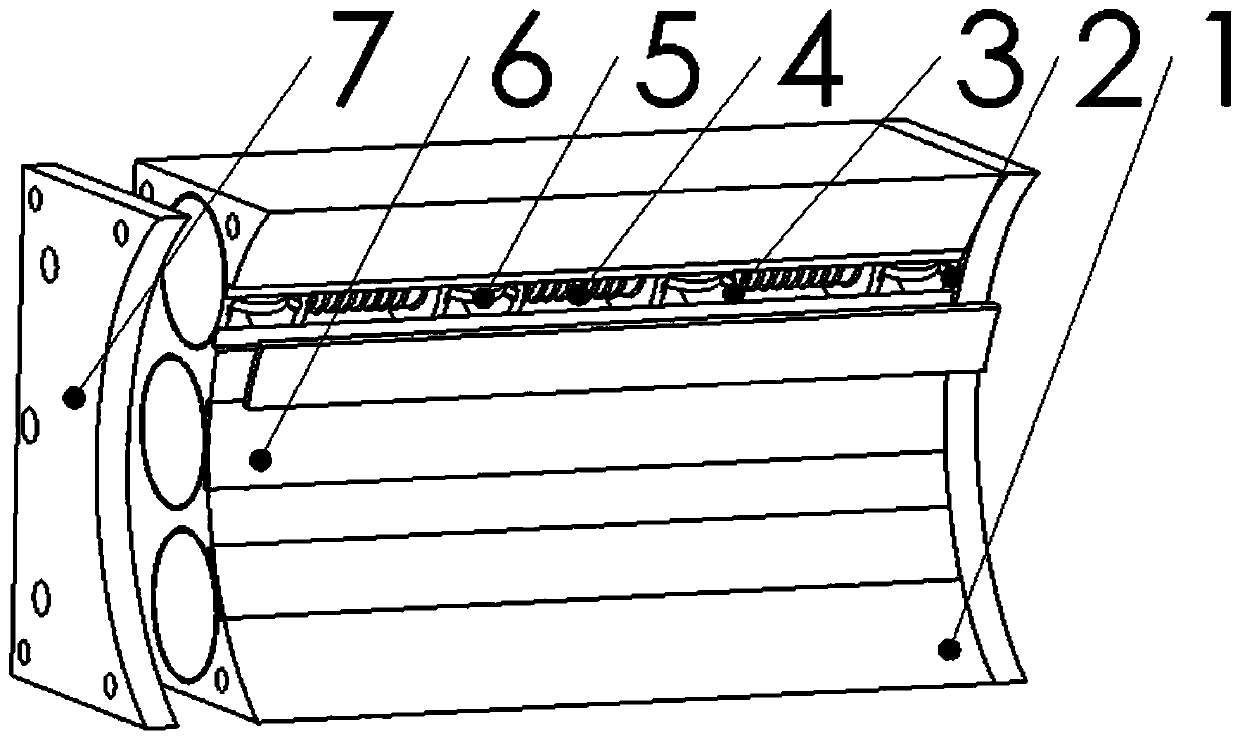
[0029] Such as figure 1 As shown, the specific implementation of the present invention includes a side push block 1, an electromagnetic briquetting unit and a rubber sheet 6; There are several strip-shaped through grooves arranged at intervals in the circumferential direction. The notch of each strip-shaped through-groove is attached with a rubber sheet 6. The rubber sheet 6 is placed between the two sides of the strip-shaped through-groove. The rubber sheet 6 covers the strip. In the notch of the shaped through groove, the inside of the side push block 1 is equipped with a number of electromagnetic briquetting units arranged in parallel along the circumferential direction of the concave arc cylindrical surface.

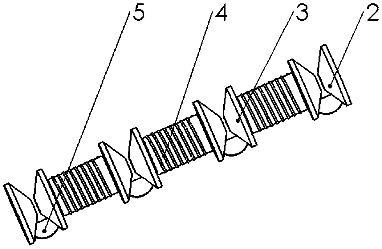
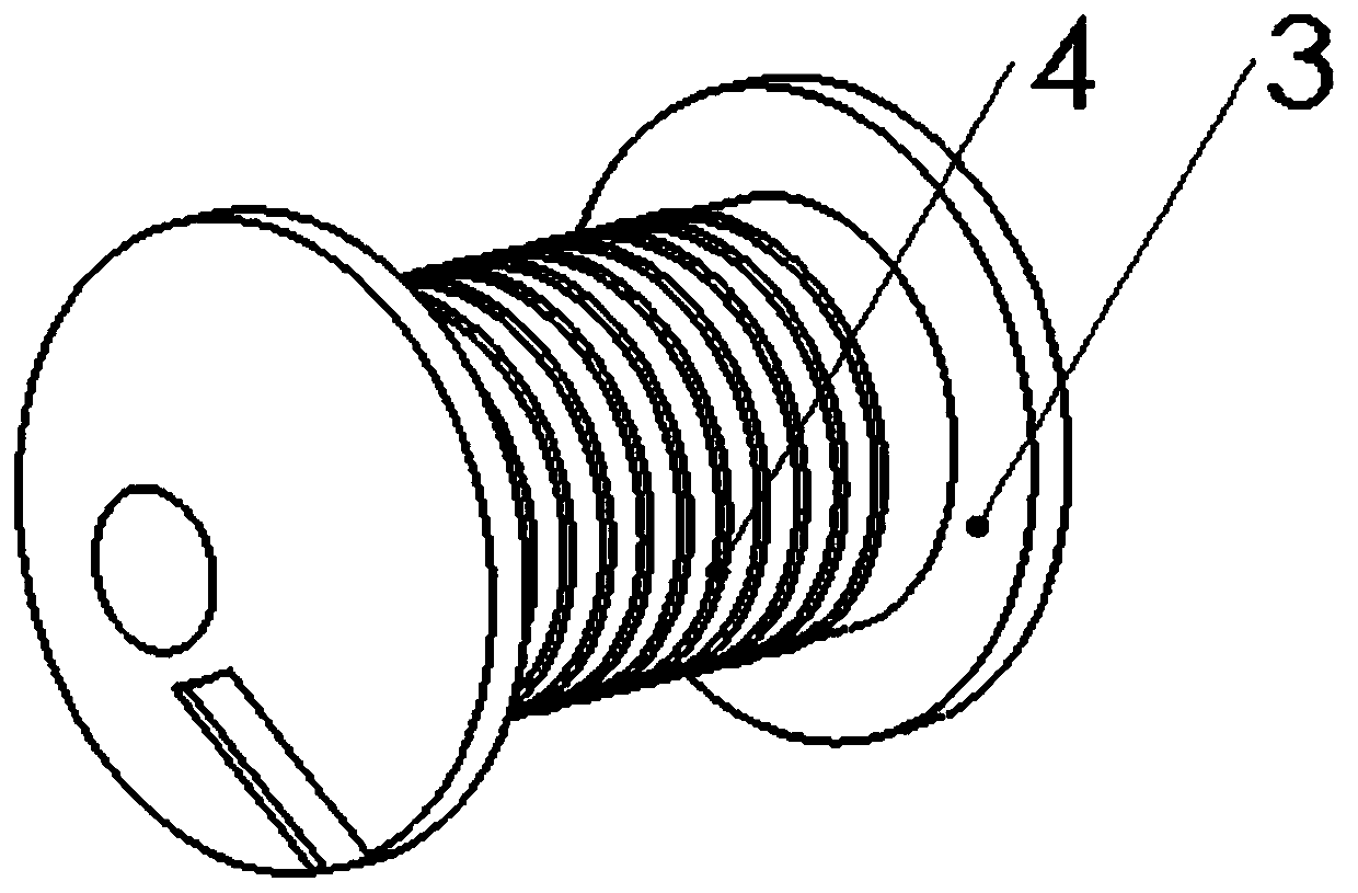
[0030] Such as figure 1 and Figure 4 As shown, each electromagnetic briquetting unit corresponds to each bar-shaped through groove, and the electromagneti...


PUM


Abstract

The invention discloses a side pushing device for bending forming of an electromagnetic type pipe fitting. The side pushing device is characterized in that the bottom surface of a side pushing block is an inward-concave arc-shaped column surface, the bottom surface of the side pushing block is in contact with the pipe fitting, a plurality of strip-shaped through grooves which are arranged at intervals in the circumferential direction are formed in the inward-concave arc-shaped column surface, and a rubber sheet is attached to a notch of each strip-shaped through groove; a plurality of electromagnetic pressing block units which are arranged in parallel at intervals in the circumferential direction of the inward-concave arc-shaped column surface are arranged inside the side pushing block, and each electromagnetic pressing block unit is arranged in parallel to the strip-shaped through grooves and is installed inside the side pushing block; and each electromagnetic pressing block unit is mainly composed of a plurality of electromagnets which are connected in series through pressing blocks to form a row, and the two ends of the series-connected electromagnets are connected with magneticbodies through the pressing blocks, and coils are wound around the electromagnets. According to the side pushing device, the stress distribution of a bending section in the bending forming process ofthe pipe fitting can be changed, so that the cross section distortion of the pipe fitting can be relieved, the thinning degree of the thickness of the outer side wall of the pipe fitting is reduced,the controllability is high, and the flexibility is high.

Description

technical field [0001] The invention relates to the technical field of bending and forming of thin-walled metal pipe fittings, in particular to an electromagnetic side pushing device for bending and forming of pipe fittings. Background technique [0002] As CNC pipe bending technology is widely used in air conditioners, automobiles, aviation, ships and other fields, pipe bending occupies an increasingly important position in industrial development, so the quality and performance of pipe bending will directly affect the structural rationality of industrial products performance, safety and reliability. [0003] During the bending and forming process of pipe fittings, there will be many defects, mainly including thinning or even cracking of the wall thickness of the outer material of the bending section under tension, increased wrinkling of the inner wall thickness under compression, springback of the pipe fittings, and cross-sectional distortion. [0004] When the pipe is ben...

Claims


Application Information

Patent Timeline
Patent Type & Authority Patents(China)
IPC IPC(8): B21D7/16B21D7/12B21D7/00
CPCB21D7/00B21D7/12B21D7/16
Inventor 张树有周会芳伊国栋
Owner ZHEJIANG UNIV
Learn More