Suction cup sucking device

A suction cup and disc body technology is applied in the field of negative pressure adsorption to achieve the effect of enhancing negative pressure balance and improving reliability.

Pending Publication Date: 2018-09-04
苏州奥特科然医疗科技有限公司
View PDF1 Cites 2 Cited by
  • Summary
  • Abstract
  • Description
  • Claims
  • Application Information

AI Technical Summary

Problems solved by technology

[0004] However, when a plurality of air-permeable materials are stacked together and are sucked and transported by the above-mentioned suction cups, due to the light weight and air permeability of the air-permeable materials, the suction cups will absorb multiple sheets at one time, which cannot meet the needs of only carrying one air-permeable material at a time. Case

Method used


Image

  • Suction cup sucking device
  • Suction cup sucking device
  • Suction cup sucking device

Examples


Embodiment 1

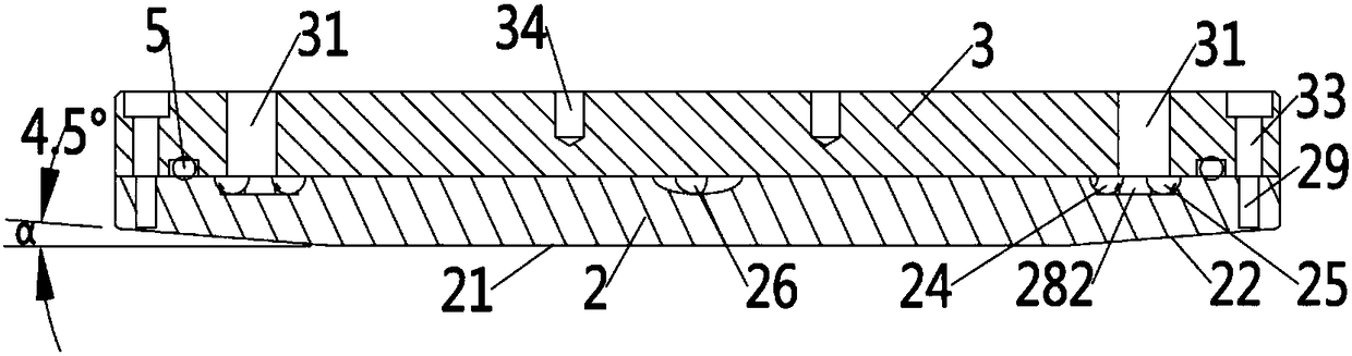
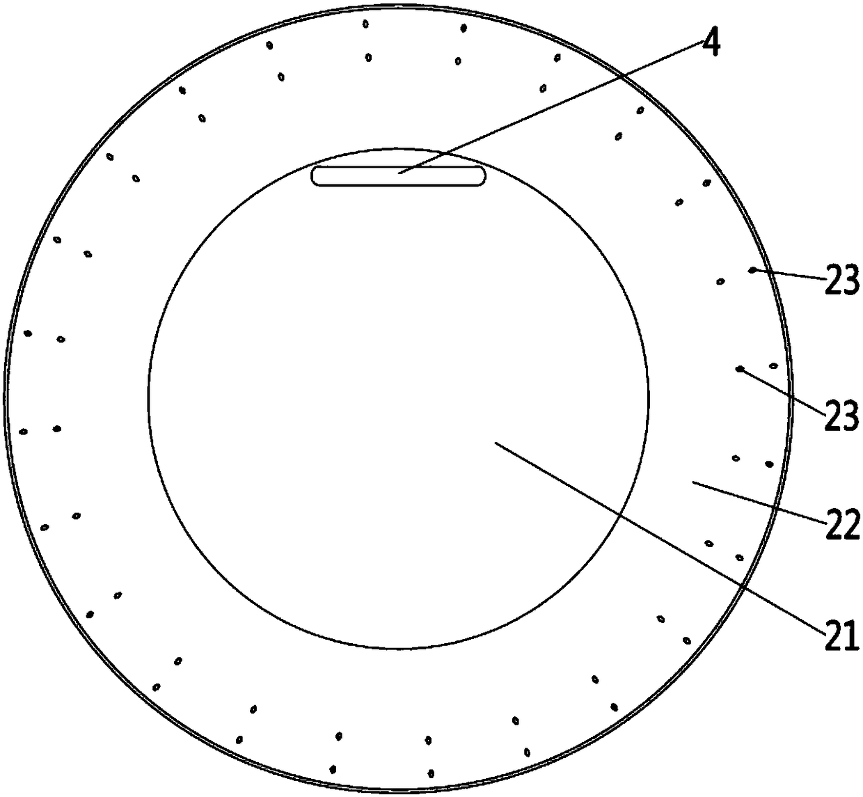
[0051] This embodiment provides a suction cup, such as figure 1 As shown, it includes a main body, and the main body includes a first disc body 2 , a second disc body 3 and a sealing ring 5 . A hollow cavity is formed between the second disc body 3 and the first disc body 2 .

[0052] Such as figure 1 , Figure 4 as well as Figure 5 As shown, the second disc body 3 is provided with an air extraction hole 31 , a sealing groove 32 , a first through hole 33 and a third through hole.

[0053] The second disc body 3 is preferably a disc-shaped structure, and its two circular surfaces serve as the inner wall surface and the outer wall surface respectively.

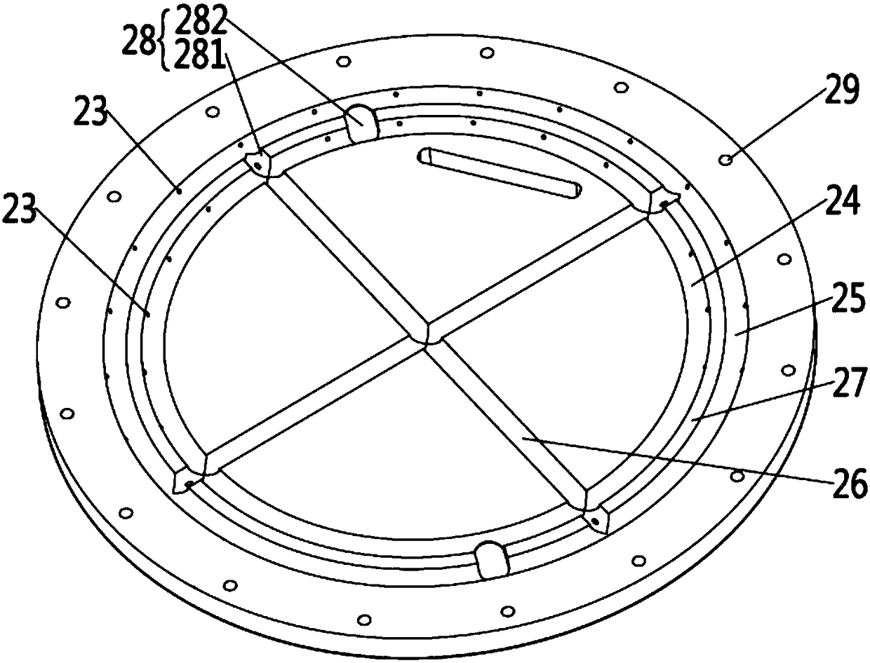
[0054] The outer peripheral edge of the second disc body 3 is provided with first through holes 33 extending from the inner wall surface to the outer wall surface, for example, several first through holes 33 are evenly distributed along the circumference of the second disc body 3, and the first through holes 33 for coopera...

Embodiment 2

[0072] This embodiment provides a suction device. Compared with the structure of the suction device provided in Embodiment 1, the only difference is that the detection device may not include a light-emitting element and a photosensitive element, but uses a weight detection element to pair the suctioned The air-permeable material is weighed, and the number of sheets of the air-permeable material absorbed is measured by weighing. At this time, the detection hole 4 can be cancelled.

Embodiment 3

[0074] This embodiment provides a suction cup. Compared with the structure of the suction cup provided in Embodiment 1 or 2, the only difference is that the angle α formed between the support surface 21 and the adsorption surface 22 is 3°; further The included angle α formed between the support surface 21 and the adsorption surface 22 is 9°; further, it can be 4°, 6° and other angles in the range of 3°-9°.


PUM


Abstract

The invention discloses a suction cup sucking device. A suction cup comprises a main body provided with a hollow inner cavity; the surface of one side of the main body is provided with a supporting surface and a sucking surface arranged on the periphery of the supporting surface, the sucking surface is warped upwards and outwards relative to the supporting surface from the supporting surface and provided with sucking holes communicating with the hollow inner cavity, and other surfaces are provided with exhaust holes communicating with the hollow inner cavity. The sucking device comprises the suction cup, and a vacuumizing device connected with the exhaust holes. Negative pressure is formed in the hollow inner cavity so that sucking force can be generated on the sucking surface; when one ofstacked breathable materials is sucked, due to the fact that the sucking surface is arranged on the periphery of the supporting surface, the zones, corresponding to the periphery of the sucking surface, of the breathable material are sucked at first due to sucking force, the peripheral zones of the stacked breathable material are obliquely warped upwards relative to the center zone of the stackedbreathable material, the other stacked breathable materials are separated from the uppermost breathable material under the action of self gravity and material stress, and the effect that the suctioncup sucks only the uppermost breathable material at a time is ensured.

Description

technical field [0001] The invention belongs to the technical field of negative pressure adsorption, and in particular relates to a suction cup and a suction device. Background technique [0002] Breathable materials, such as non-woven materials, are widely used in medical protection, military, civilian and other fields. In the production related to breathable materials, vacuum suction cups are usually used to transfer breathable materials to effectively improve the efficiency of workpieces and parts in automated and semi-automated production; at the same time, vacuum adsorption is clean, stable and reliable, and does not damage the surface of the adsorbed object. Etc. [0003] Chinese patent document CN206466763U discloses a pneumatic cloth suction cup, which includes a suction cup main body, a deflector plate and a suction plate. Among them, the suction plate is installed on the bottom of the suction cup body, and forms a negative pressure chamber with the suction cup bo...

Claims


Application Information

Patent Timeline
Patent Type & Authority Applications(China)
IPC IPC(8): B25J15/06
CPCB25J15/0683
Inventor 卫晓峰
Owner 苏州奥特科然医疗科技有限公司
Why Eureka
Try Eureka