Wind power blade web plate, wind power blade and a die for preparing wind power blade web plate

A technology of wind turbine blades and webs, applied in the field of wind power generation, can solve problems such as the inability to meet the structural design requirements of large wind turbine blades, poor reliability and safety of wind turbine blades, and increased structural safety risks, so as to improve safety and reliability Sex, avoid the effects of small support range and simple structure

Active Publication Date: 2018-09-04
ZHUZHOU TIMES NEW MATERIALS TECH
View PDF6 Cites 2 Cited by
  • Summary
  • Abstract
  • Description
  • Claims
  • Application Information

AI Technical Summary

Problems solved by technology

[0002] At present, wind turbine blades are gradually developing towards large-scale, the length of the blades is getting longer and longer, and the load on the blades is also increasing. However, the existing structure of the main beam and two webs of wind turbine blades cannot meet the structural design requirements of large wind turbine blades.
Specifically: (1) The "I-beam" web structure cannot meet the design requirements; (2) For wind turbine blades with large megawatts and large chord lengths, the structural safety risk will increase significantly
Especially in the area near the maximum chord length of the blade, the blade is prone to frequent structural problems under complex wind conditions, especially when the blade is greatly deformed under wind load operations, buckling and structural damage of the trailing edge often occur in the area of ​​​​the maximum chord length trailing edge and other problems, making the reliability and safety of wind turbine blades poor during operation

Method used


Image

  • Wind power blade web plate, wind power blade and a die for preparing wind power blade web plate
  • Wind power blade web plate, wind power blade and a die for preparing wind power blade web plate
  • Wind power blade web plate, wind power blade and a die for preparing wind power blade web plate

Examples


Embodiment Construction

[0029] The present invention will be described in further detail below in conjunction with the accompanying drawings and specific embodiments, but the protection scope of the present invention is not limited thereby.

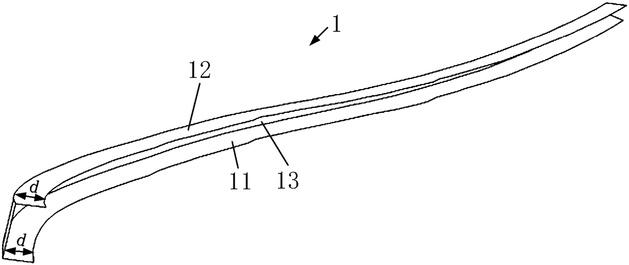
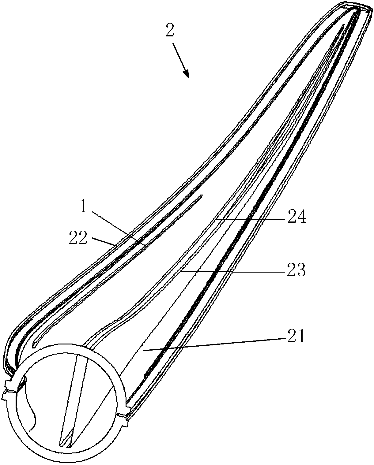
[0030] figure 1 The embodiment of the web of the wind power blade of the present invention is shown, the wind power blade web 1 is set in the cavity of the wind power blade 2 to play a supporting role, and bears the main load of the wind power blade 2 during the movement. In this embodiment, the wind turbine blade web 1 includes a suction surface bonding section 11 , a pressure surface bonding section 12 and a connecting curved surface section 13 . Wherein, the suction surface bonding section 11 is bonded to the blade suction surface; the pressure surface bonding section 12 is bonded to the blade pressure surface; the connecting curved surface section 13 is arranged between the suction surface bonding section 11 and the pressure surface bonding section 12, And ...


PUM


Abstract

The invention provides a wind power blade web plate, a wind power blade and a die for preparing the wind power blade web plate. The wind power blade web plate comprises a suction face adhesion sectionadhering to a blade suction face, a pressure face adhesion section adhering to a blade pressure face, and a connection hook face section arranged between the suction face adhesion section and the pressure face adhesion section, and the hook face of the connection hook face section is arranged along the bending trajectory of the rear edge of the blade. The wind power blade comprises a blade shelland the wind power blade web plate, the wind power blade web plate is supported in an area on the rear edge inside the blade shell, and the connection hook face section of the wind power blade web plate is parallel to the rear edge of the blade shell. The die for preparing the wind power blade web plate comprises a bent bottom plate, a suction face baffle and a pressure face baffle, the hook faceof the bent bottom plate is arranged along the bending trajectory of the rear edge of the blade, and the suction face baffle and the pressure face baffle are oppositely arranged on the upper surface of the bent bottom plate. The advantages that the blade baring capacity is high, and safety and reliability are high are achieved.

Description

technical field [0001] The invention relates to the technical field of wind power generation, in particular to a wind power blade web, a wind power blade and a mold for preparing the wind power blade web. Background technique [0002] At present, wind turbine blades are gradually developing towards large-scale, the length of the blades is getting longer and longer, and the load on the blades is also increasing. However, the existing structure of the main beam and two webs of wind turbine blades cannot meet the structural design requirements of large wind turbine blades. Specifically: (1) The "I-beam" web structure cannot meet the design requirements; (2) For wind turbine blades with large megawatts and large chord lengths, the structural safety risk will increase significantly. Especially in the area near the maximum chord length of the blade, the blade is prone to frequent structural problems under complex wind conditions, especially when the blade is greatly deformed under...

Claims


Application Information

Patent Timeline
Patent Type & Authority Applications(China)
IPC IPC(8): B29C33/42F03D1/06B29L31/08
CPCB29C33/42B29L2031/082F03D1/0675Y02E10/72
Inventor 凡盛侯彬彬梁鹏程胡杰桦谭龙彭勃肖琼李东旭易礼毅王岩
Owner ZHUZHOU TIMES NEW MATERIALS TECH
Why Eureka
Try Eureka