Electric vehicle high-voltage interlocking loop and open circuit positioning method

A high-voltage interlocking circuit, electric vehicle technology, applied in electric vehicles, measuring electricity, power-consuming devices, etc., can solve the problem of inability to accurately locate the fault of high-voltage connectors

Inactive Publication Date: 2018-09-04
SHANDONG TRANSPORT VOCATIONAL COLLEGE
View PDF6 Cites 7 Cited by
  • Summary
  • Abstract
  • Description
  • Claims
  • Application Information

AI Technical Summary

Problems solved by technology

[0004] Aiming at solving the problem in the prior art that it is impossible to accurately locate which high-voltage connector is faulty, the first technical problem solved by the present invention is to provide a high-voltage interlock circuit for electric vehicles, which is used for the high-voltage circuit of electric vehicles. Servicing and Troubleshooting Provides Reference

Method used


Image

  • Electric vehicle high-voltage interlocking loop and open circuit positioning method
  • Electric vehicle high-voltage interlocking loop and open circuit positioning method
  • Electric vehicle high-voltage interlocking loop and open circuit positioning method

Examples


Embodiment 1

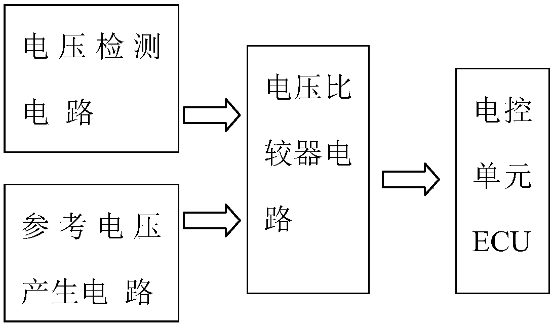
[0048] Such as figure 1 As shown, a high-voltage interlock circuit of an electric vehicle, the high-voltage interlock circuit is a low-voltage electrical connection circuit independent of the high-voltage circuit of the electric vehicle, including a voltage detection circuit, a reference voltage generation circuit, a voltage comparator circuit and an electronic control unit ECU; the detection voltage of the voltage detection circuit and the reference voltage of the reference voltage generation circuit are used as the input signal of the voltage comparator in the voltage comparator circuit, and the output signal of the voltage comparator is used as the input signal of the electronic control unit ECU.

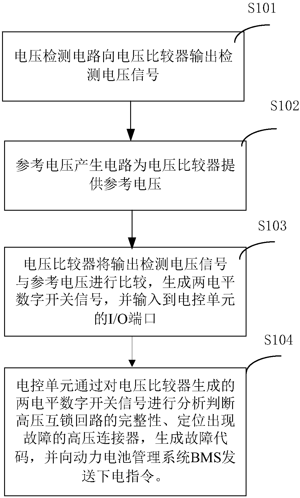
[0049] figure 2 It shows the flow chart of the high-voltage interlock open circuit positioning method of the high-voltage interlock circuit of the electric vehicle provided by the first embodiment of the present invention, and its specific steps are as follows:

[0050] In step...

Embodiment 2

[0057] On the basis of the above-mentioned first embodiment, further optimization is performed, and the positioning detection is mainly performed on the four high-voltage connectors in the electric vehicle.

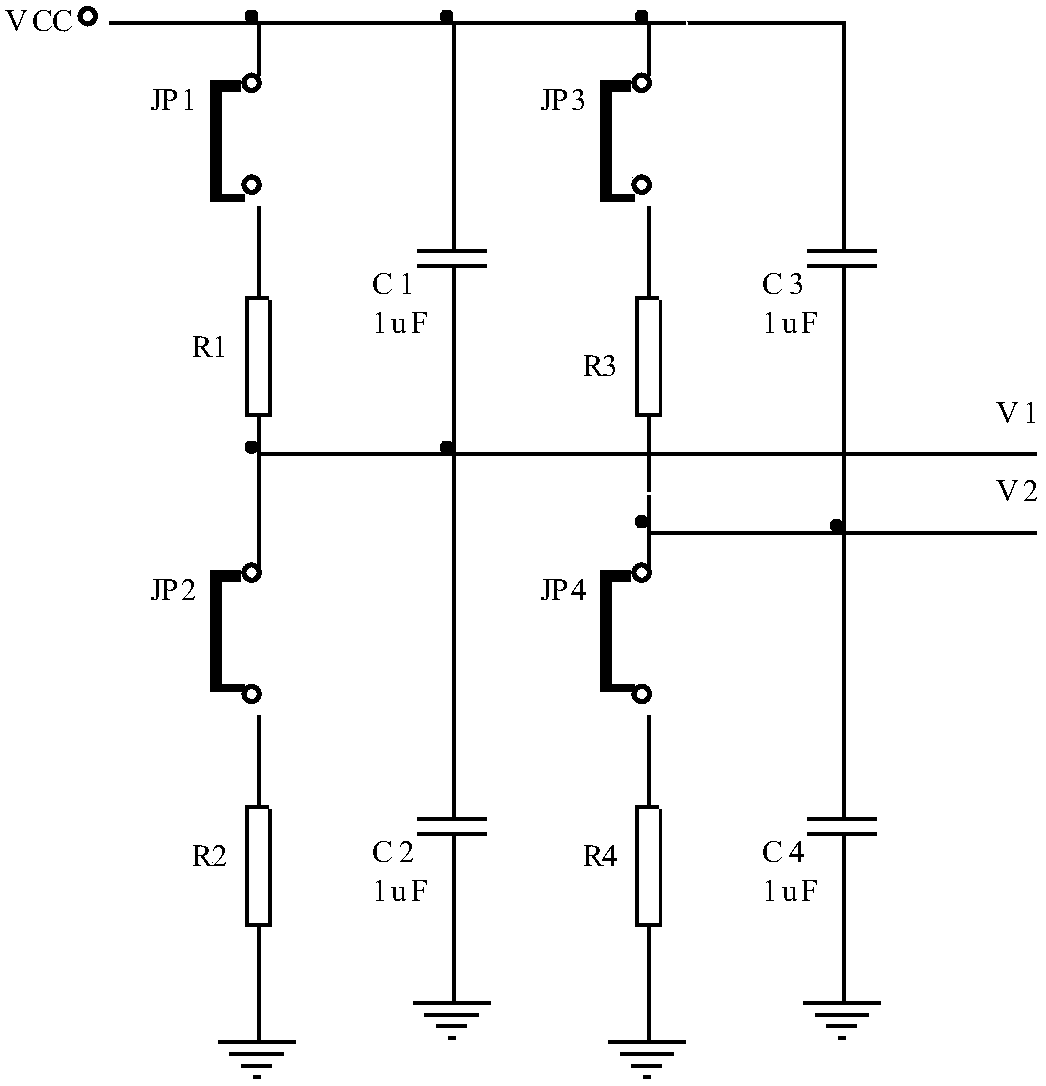
[0058] Such as image 3 As shown, the voltage detection circuit includes a first-stage voltage detection circuit and a second-stage voltage detection circuit connected in parallel, one end of the first-stage voltage detection circuit and the second-stage voltage detection circuit are electrically connected to the low-voltage power supply Vcc, and the other ends are grounded .

[0059] The voltage detection circuit includes a first-stage voltage detection circuit and a second-stage voltage detection circuit connected in parallel, one end of the first-stage voltage detection circuit and the second-stage voltage detection circuit are both electrically connected to the low-voltage power supply, and the other ends are both grounded;

[0060] The first-stage voltage detection ...


PUM


Abstract

The invention discloses an electric vehicle high-voltage interlocking loop and an open circuit positioning method. The high-voltage interlocking loop comprises a voltage detecting circuit, a referencevoltage generating circuit, a voltage comparator circuit and an electric control unit. The open circuit positioning method includes the steps that the voltage detecting circuit outputs a detecting voltage signal to a voltage comparator in the voltage comparator circuit; the reference voltage generating circuit outputs a reference voltage signal to the voltage comparator in the voltage comparatorcircuit; the voltage comparator compares the detecting voltage signal with the reference voltage signal to generate a two-level digital switch signal to be input to the electronic control unit. The electronic control unit analyzes the two-level digital switch signal generated by the voltage comparator to judge the integrity of the high-voltage interlocking loop, and then judges the integrity of anelectric vehicle high-voltage loop, and a reference is provided for maintenance and troubleshooting of the electric vehicle high-voltage loop.

Description

technical field [0001] The invention belongs to the technical field of high-voltage safety control of electric vehicles, and in particular relates to a high-voltage interlock circuit of electric vehicles and a circuit breaker positioning method. Background technique [0002] The high-voltage interlock circuit is a safety design measure for electric vehicles that uses low-voltage signals to monitor the integrity of the high-voltage circuit. Its monitoring target is the high-voltage connector in electric vehicles that requires human operation to switch on and off the circuit. During the vehicle power-on or charging process, if the high-voltage interlock circuit detects that the high-voltage circuit is incomplete, the system cannot be powered on or charged to avoid accidents due to problems such as virtual connections; if the vehicle collides and the high-voltage connector is loosened or repaired The high-voltage connector is loosened due to misoperation by the operator. By det...

Claims


Application Information

Patent Timeline
Patent Type & Authority Applications(China)
IPC IPC(8): B60L3/00B60L11/18G01R31/04
CPCB60L3/00B60L58/10G01R31/67Y02T10/70
Inventor 杨效军房伟萍
Owner SHANDONG TRANSPORT VOCATIONAL COLLEGE
Why Eureka
Try Eureka