Straddle type monorail track beam, manufacturing method thereof and monorail system

A straddle-type monorail and track beam technology, which is applied in the field of rail transit, can solve problems such as concrete pouring at wet joints, difficulty in vibration, impact on driving comfort, and increased difficulty of construction, so as to achieve simple structure and enhance overall stability Sexuality, the effect of less post-maintenance

Pending Publication Date: 2018-09-04
CHINA CONSTR FIFTH ENG DIV CORP LTD
View PDF0 Cites 4 Cited by
  • Summary
  • Abstract
  • Description
  • Claims
  • Application Information

AI Technical Summary

Problems solved by technology

[0004] However, the joint between the steel plate 2 and the concrete is misaligned, rainwater infiltrates and corrodes the first steel bar 3 of the beam body, and the steel plate is easy to warp and produce concave-convex deformation under the action of the live load of the vehicle, and the phen

Method used


Image

  • Straddle type monorail track beam, manufacturing method thereof and monorail system
  • Straddle type monorail track beam, manufacturing method thereof and monorail system
  • Straddle type monorail track beam, manufacturing method thereof and monorail system

Examples


Embodiment 1

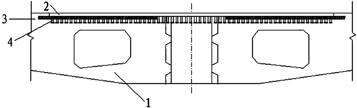
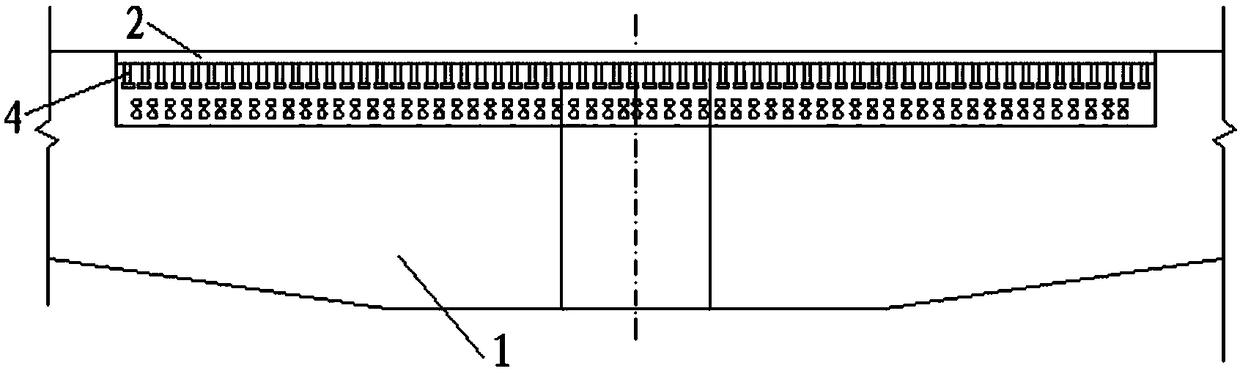
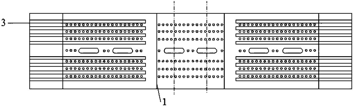
[0035] Figure 4 Shown is the top sectional view at the wet joint of the straddle type monorail track beam of the present invention; as Figure 4 and Figure 5 As shown, the straddle-type monorail track beam includes: a plurality of corrugated pipes and a plurality of steel strands 5; so that the end of the corrugated pipe is not on the same cross-section of the track beam 1; the corrugated pipe in the track beam 1 of the adjacent span is connected with the corrugated pipe in the wet joint at the pier, and the steel strand 5 passes through the adjacent span The bellows in the track beam 1 and the bellows in the wet joint; and the ends of the steel strands 5 are respectively anchored at the top surface of the adjacent span track beam 1 .

[0036] Specifically, in Figure 4 and Figure 5 In order to facilitate the display of strand 5, in Figure 4 and Figure 5 The corrugated pipe is omitted in , but the direction of the corrugated pipe is consistent with the steel strand ...

Embodiment 2

[0044] like Image 6 As shown, the present invention also provides a method for manufacturing a straddle type monorail track beam, including: S1, pre-embed a plurality of bellows in the top plate of the track beam 1, and the ends of the bellows are arranged in a staggered manner on the track at the roof of the beam 1; S2, pouring wet joints at the pier, and pre-embedding multiple bellows in the wet joints; and connecting the bellows in the track beam 1 with the bellows in the wet joints; The wire is inserted into the bellows in the track beam 1 of the adjacent span and the bellows in the wet joint to connect the track beam 1 of the adjacent span and the wet joint; The ends of the wires 5 are respectively anchored at the top surfaces of the track beams 1 of adjacent spans. And, the step S3 further includes: filling the gap between the corrugated pipe and the steel strand.

[0045] Specifically, the bellows are pre-embedded in the top plate of the track beam 1, that is, when t...


PUM


Abstract

The invention relates to the field of rail transit, and discloses a straddle type monorail track beam, a manufacturing method of the straddle type monorail track beam and a monorail system. The straddle type monorail track beam includes a plurality of bellows and a plurality of steel strands; the bellows are pre-embedded in a top plate of the track beam, and the ends of the bellows are staggeredlyarranged at the top plate of the track beam, so that the ends of the bellows are not on the same cross section of the track beam; the steel strands are interspersed in the adjacent bellows of the track beam for connecting wet joints at the adjacent span track beam and bridge piers; the ends of the steel strands are respectively anchored to the top surface of the adjacent span track beam. The straddle type monorail track beam can effectively resist the tensile stress generated by the negative bending moment at the top plate, the top plate can be effectively prevented from cracking, the rainwater is prevented from invading and damaging a beam body, and the service life of the track beam is prolonged.

Description

technical field [0001] The invention relates to the field of rail transportation, in particular to a straddle monorail track beam, a manufacturing method of the straddle monorail track beam and a monorail system. Background technique [0002] Straddle-type monorail traffic is a new urban traffic mode. Compared with conventional public transportation on the ground, it has the advantages of large transportation capacity, fast speed, and strong climbing ability. At the same time, it can effectively alleviate urban traffic congestion and save energy. People travel time. The line section generally adopts an elevated bridge structure. The vehicle running wheels are supported above the track beam, and the stabilizing wheels and guide wheels act on both sides of the track beam respectively. The way of the beam-holding driving greatly improves the safety of the vehicle during operation. [0003] like figure 1 As shown, the track beam 1 is not only the running track of the vehicle b...

Claims


Application Information

Patent Timeline
IPC IPC(8): E01B25/10E01D19/02E01D21/00
CPCE01B25/10E01D19/02E01D21/00
Inventor 周帅凡林李水生谭立新方聪
Owner CHINA CONSTR FIFTH ENG DIV CORP LTD
Why Eureka
Try Eureka