
Core pipe valve

A core tube and valve core tube technology, applied in the field of core tube valves, can solve the problems of difficult diaphragm manufacturing process, prolonged load relief, early load relief, etc., and achieves the effect of being beneficial to intelligent manufacturing, reducing pollution and reducing investment.

Active Publication Date: 2018-09-04
卢星霖
View PDF5 Cites 15 Cited by
  • Summary
  • Abstract
  • Description
  • Claims
  • Application Information

AI Technical Summary

Problems solved by technology

[0024] Disadvantages: ①Because of the valve body lining process and diaphragm manufacturing process and restrictions, the larger valve body lining and larger diaphragm manufacturing process are difficult, so the diaphragm is not suitable for larger pipe diameters, generally used in DN≤200mm On the pipeline below; ② Due to the limitation of the diaphragm material, the diaphragm valve is suitable for low pressure and low temperature occasions; generally not exceeding 180 °C; ③ The adjustment performance is relatively poor, and it can only be adjusted in a small range (generally closed to 2 / 3 opening, can be used for flow regulation)
[0028] Disadvantages of compression spring direct load safety valve: the load will change with the opening, that is, the compression spring force will increase gradually during the opening process, resulting in poor discharge, and the opening height, discharge time and speed cannot be adjusted on site; during use The fatigue of the medium metal compression spring changes greatly and the pressure limiting parameters fluctuate greatly. It must be adjusted frequently to ensure normal use, otherwise there will be premature discharge or prolonged discharge
[0029] The disadvantages of pilot-operated safety valves are: the sealing rubber of the O-shaped rubber ring has poor temperature resistance; the structure is complex and the manufacturing cost is high; low sensitivity
[0053] At present, the valves used in pipelines such as submarines, nuclear energy, toxic and harmful media, flammable and explosive media, and urban water supply do not have a two-way burst pipe automatic cut-off valve. Slow, the control system itself also has faults, and the reliability is difficult to be fully guaranteed; the two-way squib automatically cuts off the core pipe valve can solve this problem, the automatic here means that through the medium energy of the pipeline itself, no other resources are required , control systems and control equipment
[0054] At present, exhaust valves and steam traps are all of the buoy type, which has a small flow caliber, a large valve volume, and is easy to block and wear on the sealing surface. Especially high temperature and high pressure steam traps are difficult problems in industrial applications. The core tube valve and the drain core tube valve can satisfactorily solve these two problems respectively
[0055] At present, safety valves, especially large-diameter safety valves, use spring type safety valves with poor reliability, and pilot-type safety valves are too complicated; safety core tube valves can satisfactorily solve the problems from miniature to large and super large safety valves
[0056] At present, a pipeline is connected in series with valves for many purposes, such as opening and closing valves, pressure reducing valves, regulating valves, balance valves, check valves, and emergency shut-off valves, which not only wastes resources, but also causes flow resistance, increasing failure rates and maintenance costs; A function variant core tube valve can satisfactorily solve this problem

Method used


Image

  • Core pipe valve
  • Core pipe valve
  • Core pipe valve

Examples


Embodiment 1

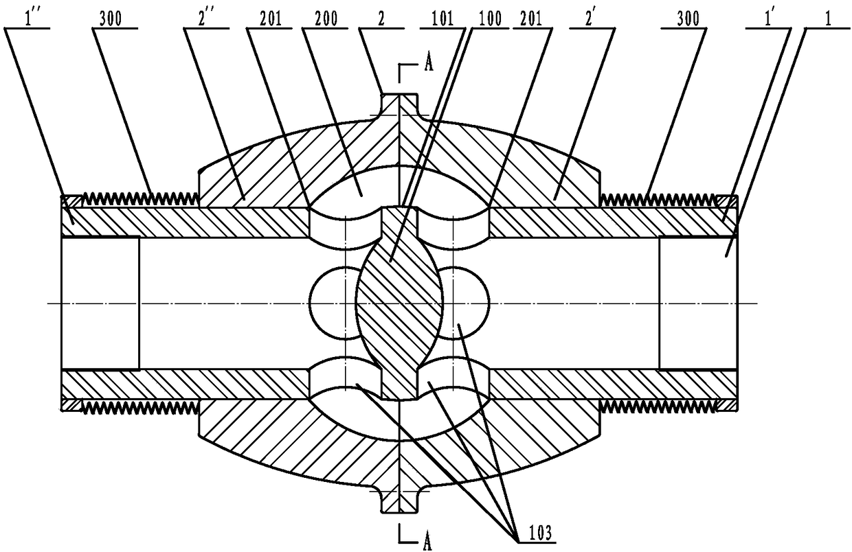
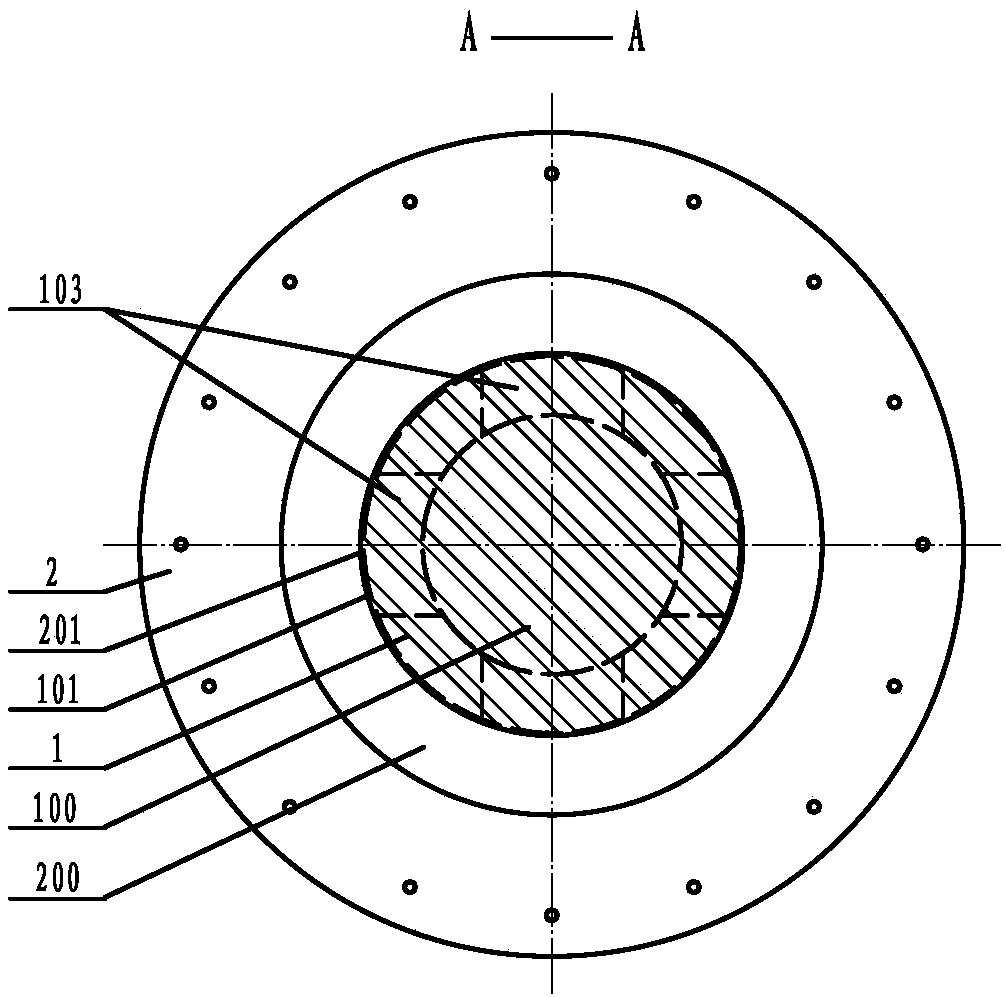
[0235] See attached figure 1 , 2 , the core tube valve described in this embodiment, the valve core tube 1 is a sleeve tube I2' coaxially penetrating through the valve body 2, the inner cavity 200 of the valve body 2, and the sleeve tube II2" of the valve body 2; There is an axial partition 100 in the middle of the core tube 1, and the two axial end faces of the inner core of the partition 100 are spherical surfaces; the axially adjacent two sides of the partition 100 are respectively four radial flow passages of the input section 1' and the output section 1". The hole 103; the sealing surface of the annular valve core 101 surrounding and integrated with the interlayer 100 is a two-way slope surface and the annular valve seat 201 at the throat of the sleeve pipe I2' and the sleeve pipe II2 "all constitute a sealing pair; the input section 1' and the sleeve pipe Ⅰ2′, output section 1″ and sleeve Ⅱ2″ are shaft-hole fit, and bellows seals 300 are provided at the joints; the shap...

Embodiment 2

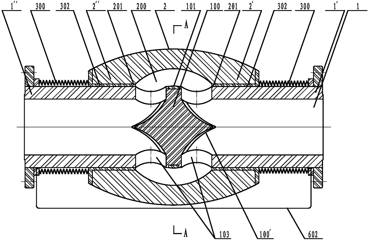
[0239] See attached image 3 , 4 , the core tube valve described in this embodiment, the shape of the inner cavity 200 is spherical and wraps the partition 100 and the flow hole 103 in the open state; the two axial end faces of the inner core of the partition 100 are tongue-shaped triangular slopes 100 '; the axially adjacent two sides of the interlayer 100 are respectively two radial flow holes 103 of the input section 1' and the output section 1 "; the sealing surface of the annular valve core 101 surrounding and embedded in the interlayer 100 is a bidirectional slope surface The annular valve seat 201 at the throat of the sleeve tube I2' and the sleeve tube II2" both constitute a sealing pair; the joints of the input section 1' and the sleeve tube I2' and the output section 1" and the sleeve tube II2" are provided with bellows seals 300 and sealing rings 302 , a connecting tube 602 runs through the inner cavities of the two bellows seals 300; the sleeve I2' and the sleeve ...

Embodiment 3

[0243] See attached Figure 5 , 6 , the core tube valve described in this embodiment, the longitudinal shape of the inner cavity 200 is a round cake shape, which wraps the interlayer 100 and the flow hole 103 in the open state, and its thickness is greater than or equal to the diameter of the annular valve core 101; the interlayer 100 inner core The two axial end surfaces of the two axial ends are tongue-shaped triangular slope surfaces 100'; the axially adjacent two sides of the interlayer 100 are respectively two radial flow holes 103 of the input section 1' and the output section 1"; surrounding and connecting with the interlayer 100 The sealing surface of the integrated annular valve core 101 is a circular arc slope and the annular valve seat 201 at the throat of the sleeve pipe I2' and the sleeve pipe II2" all constitute a sealing pair; the input section 1' and the sleeve pipe I2' and the output section 1" and the Bellows seals 300 are provided at the junctions of the sl...


PUM


Abstract

The invention provides a core pipe valve, and belongs to the field of valves. The core pipe valve is an original brand-new-structure valve, and refers to starting and stopping, pressure starting and stopping, adjustment, safety, decompression, returning stopping, pressure reduction, emergency cutting-off and the like. A valve element pipe is a fixing piece and coaxially penetrates through a sleeveI of a valve body, a valve body cavity and a sleeve II of the valve body; an axial partition is arranged in the middle of the valve element pipe, and two adjacent sides of the partition in the axialdirection are separately at least one radial circulating hole of a pipe section I and at least one radial circulating hole of a pipe section II; an annular valve element which surrounds the partition,an annular valve seat of at least one sleeve throat of the sleeve I and an annular valve seat of at least one sleeve throat of the sleeve II form a sealing pair; the difference between the outer diameters of the pipe section I and the pipe section II is greater than or equal to 0, the pipe section I is in shaft hole type fit with the sleeve I, the pipe section II is in shaft hole type fit with the sleeve II, and at least one combined portion is provided with a seal; and under the effect of two direction potential energy, the valve body axially moves in an axial direction relative to the valveelement pipe to implement starting and stopping and function transformation. The core pipe valve is simple in structure, convenient to manufacture, low in starting and stopping resistance and good insafety, reliability and sensitivity, and adapts to various working conditions, and the efficiency is improved.

Description

technical field [0001] The core tube valve of the present invention belongs to the field of valves. The core tube valve is an original new structure following the plug valve, globe valve, gate valve, butterfly valve, ball valve and diaphragm valve and has strong common technical characteristics. It will be used as a A huge series of valves has been released to the world, and the common technical characteristics of core tube valves will at least make the structural design of two-way valves span from the "Kingdom of Inevitability" to the "Kingdom of Freedom". [0002] The six characteristics of the core tube valve are lacking or not available in the existing six types of valves: plug valve, globe valve, gate valve, butterfly valve, ball valve and diaphragm valve: 1. No matter how much the medium pressure or the ambient pressure is, it has the characteristics of easy and fast opening and closing ; 2. Two-way opening and closing characteristics that can be realized; 3. External se...

Claims


Application Information

Patent Timeline
IPC IPC(8): F16K3/02F16K3/314F16K31/62F16K31/06
CPCF16K3/02F16K3/314F16K31/0668F16K31/62
Inventor 卢星霖
Owner 卢星霖
Learn More