Adjustable two-way float valve and working method thereof

A float valve and adjustable technology, applied in the direction of the float of the control valve, the operation/release device of the valve, the lift valve, etc., to achieve the effect of accelerating separation, reducing the labor intensity of workers, and ensuring the quality of separation

Pending Publication Date: 2018-09-04
XI'AN PETROLEUM UNIVERSITY
View PDF8 Cites 1 Cited by
  • Summary
  • Abstract
  • Description
  • Claims
  • Application Information

AI Technical Summary

Problems solved by technology

[0003] In order to overcome the problems of liquid and gas output from the gas outlet of existing equipment, the purpose of the present invention is to provide a buoyancy-adjustable two-way float valve with simple structure, convenient installation, and automatic operation, which is used in gas-liquid separators. Among them, it can solve the engineering phenomenon of liquid out of the gas outlet and gas out of the liquid outlet, and can greatly reduce the labor intensity of workers

Method used


Image

  • Adjustable two-way float valve and working method thereof
  • Adjustable two-way float valve and working method thereof

Examples


Embodiment Construction

[0025] Below in conjunction with accompanying drawing, the present invention is described in further detail:

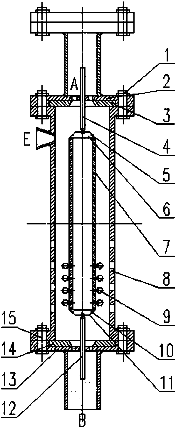
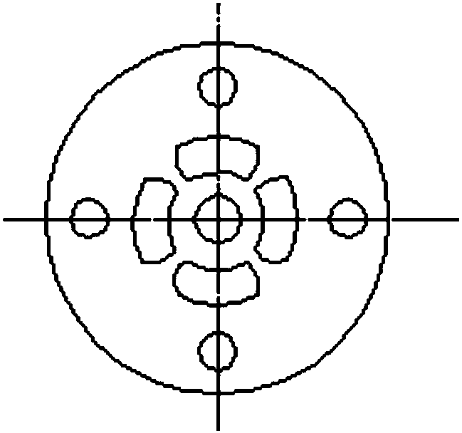
[0026] see figure 1 and figure 2 , an adjustable two-way float valve, mainly including cylinder body 8, upper valve seat 3, lower valve seat 14, upper cone valve body 6, lower cone valve body 11, float cylinder 7, upper flexible guide rod 4, lower flexible guide rod Rod 12, buoyancy regulator 9.

[0027] There is a gas acceleration port E on the top of the cylinder 8, with a taper of 10° to 25°, and several liquid inlets below; the upper valve seat 3 and the lower valve seat 14 are respectively pressed against the upper flange 2 and the lower flange 13. The upper and lower ends of the cylinder 8, the upper flange 2 is connected with the upper end of the cylinder 8 through several upper bolts 1, the lower flange 13 is connected with the lower end of the cylinder 8 through several lower bolts 15, the upper flange 2, the lower flange 13 It is in the shape of a divers...


PUM


Abstract

The invention discloses an adjustable two-way float valve and a working method of the adjustable two-way float valve. The adjustable two-way float valve comprises a cylinder body, an upper valve seat,a lower valve seat and a buoyancy valve. A gas accelerating opening is formed in the upper portion of the cylinder body, and a plurality of liquid inlets are formed in the lower portion of the cylinder body. The upper valve seat and the lower valve seat abut against the upper end and the lower end of the cylinder body in a press mode through an upper flange and a lower flange correspondingly. A float valve body is arranged in the cylinder body, and comprises a float cylinder. The upper end and the lower end of the float cylinder are connected with an upper conical valve body and a lower conical valve body correspondingly, and the upper end of the upper conical valve body and the lower end of the lower conical valve body are connected with an upper flexible guide rod and a lower flexible guide rod correspondingly. A plurality of buoyancy adjustors are further arranged on the float cylinder. The upper flexible guide rod and the lower flexible guide rod are matched with guide holes formed in the middle of the upper flange and the middle of the lower flange correspondingly, the upper flange is connected to a gas outlet, and the lower flange is connected to a liquid outlet. The adjustable two-way float valve and the working method of the adjustable two-way float valve can avoid the engineering phenomena that liquid flows out of the gas outlet, and gas flows out of the liquid outlet, and can greatly reduce the labor intensity of workers.

Description

technical field [0001] The invention belongs to the field of gas-liquid separation, and in particular relates to an adjustable two-way float valve and a working method thereof. Background technique [0002] At present, most gas-liquid separators used in oil fields and refineries are generally designed according to a certain pressure and flow rate due to the fixed internal structure size. , Often there will be an engineering phenomenon that the gas outlet of the separator will emit liquid and the liquid outlet will emit gas. The liquid output from the gas outlet will cause difficulties in natural gas collection, and the gas output from the liquid outlet will cause physical injury to the workers on site. In order to reduce the occurrence of this phenomenon, the methods used on site mostly rely on workers' experience and observation to manually adjust the outlet control valve. However, due to the on-site situation, the inlet pressure and flow rate often change randomly. If the...

Claims


Application Information

Patent Timeline
Patent Type & Authority Applications(China)
IPC IPC(8): F16K31/22F16K11/044F16K1/38F16K33/00
CPCF16K1/38F16K11/044F16K31/22F16K33/00
Inventor 崔占琴张安妮韩旭
Owner XI'AN PETROLEUM UNIVERSITY
Why Eureka
Try Eureka