Fully-insulated enclosed fuse

A closed and fully insulated technology, which is applied to electrical components, circuits, emergency protection devices, etc., can solve problems such as safety performance degradation, fusion tube malfunction, power outage, and reduced service life of fuses, etc. High flow and breaking capacity, long overall service life

Pending Publication Date: 2018-09-04
江苏新澳电力技术有限公司
View PDF6 Cites 1 Cited by
  • Summary
  • Abstract
  • Description
  • Claims
  • Application Information

AI Technical Summary

Problems solved by technology

[0002] The conductors of the upper and lower dynamic and static contacts of the traditional drop-out fuse are exposed, and it is easy to hang foreign objects and trees to cause the phase-to-phase or grounding short circuit of the fuse, which is one of the key fault sources of overhead lines
In addition, the exposed conductors are prone to rust, resulting in overheating caused by poor contact, spring annealing, and overheating of the contacts will lead to a vicious cycle of increased resistance, causing the fusion tube to fall and cause a power failure, or the contacts are burnt and melted into one body. The fusion tube cannot fall off and loses its function
In addition, ordinary insulated fuses, due to the poor coordination between the arc suppression tube and the arc suppression rod during operation, the arc energy generated when the short circuit is disconnected is relatively large, which is likely to cause damage to the fuse and affect the service life of the fuse. And the fuse will generate temperature when it is working, which will cause the temperature of the fuse itself to rise and reduce the service life of the fuse, and the fuse tube is one of the important parts of the short-circuit disconnection of the fuse. If the quality of the fuse tube is poor, it is easy to cause the fuse Unable to work, reduced safety performance

Method used


Image

  • Fully-insulated enclosed fuse
  • Fully-insulated enclosed fuse

Examples


Embodiment Construction

[0014] The present invention will be further described below in conjunction with the accompanying drawings and embodiments.

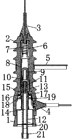
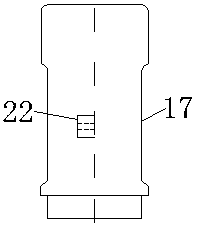
[0015] Such as figure 1 and figure 2 As shown, the fully insulated closed fuse of the present invention includes a rubber base 1, an outer insulating porcelain bottle 2 is arranged on the rubber base 1, and an upper rubber sealing incoming line is arranged on the top of the outer insulating porcelain bottle 2. The connecting piece 3 is provided with a lower rubber seal inlet connector 4 at the lower part of the outer insulating porcelain bottle 2 perpendicular to it, and a mounting bracket 5 is arranged at the middle and upper part of the outer insulating porcelain bottle 2, and a There is an upper static contact 6, an upper auxiliary spring 7 is arranged in the upper static contact 6, an arc suppression tube 8 is arranged at the lower part of the upper static contact 6, and an arc suppression tube 8 is arranged in the arc suppression tube 8 The arc ...


PUM


Abstract

The invention relates to a fully-insulated enclosed fuse comprising a rubber pedestal. An upper static contact is arranged at the upper part inside an outer insulating porcelain insulator; and an upper auxiliary spring is arranged inside the upper static contact. An arc extinguishing tube is arranged at the lower part of the upper static contact; and an arc extinguishing rod is arranged in the arcextinguishing tube. An upper moving contact is arranged at the lower end of the arc extinguishing rod and is connected with a fusion tube by a fusion tube connecting element. An arc shrinkage bar isarranged at the upper part inside the fusion tube and is connected with a fuse wire. A buffer cover is arranged at the upper part outside the fusion tube; a lower static contact is arranged at the inner side of the buffer cover; and a lower moving contact is arranged outside the fusion tube. The lower inner pipe of the fusion tube has a segmented stepped structure with the larger bottom and the smaller top. Besides, a fuse wire connection boss is arranged at one side with the central line corresponding to the straight line of the outer wall of the lower moving contact. The fully-insulated enclosed fuse has advantages of stable operation, high usage safety and reliability, powerful product carrier and breaking capabilities, and long service life.

Description

technical field [0001] The invention relates to a power equipment device, in particular to an insulating fuse. Background technique [0002] The conductors of the upper and lower dynamic and static contacts of traditional drop-out fuses are exposed, and foreign objects are easy to be caught. Trees cause phase-to-phase or grounding short circuits of the fuse, which is one of the key fault sources of overhead lines. In addition, the exposed conductors are prone to rust, resulting in overheating caused by poor contact, spring annealing, and overheating of the contacts will lead to a vicious cycle of increased resistance, causing the fusion tube to fall and cause a power failure, or the contacts are burnt and melted into one body. The fusion tube cannot fall off and loses its function. In addition, ordinary insulated fuses, due to the poor coordination between the arc suppression tube and the arc suppression rod during operation, the arc energy generated when the short circuit ...

Claims


Application Information

Patent Timeline
Patent Type & Authority Applications(China)
IPC IPC(8): H01H85/38H01H85/17H01H85/43H01H85/143H01H85/20H01H85/00
CPCH01H85/0078H01H85/143H01H85/17H01H85/2045H01H85/38H01H85/43
Inventor 朱志伟邢强肖志勇
Owner 江苏新澳电力技术有限公司
Why Eureka
Try Eureka