
Bent T-shaped rotating structure based directional circularly polarized antenna

A technology of circularly polarized antenna and rotating structure, which is applied in the structural form of radiating elements, antenna support/mounting device, antenna grounding switch structural connection, etc., which can solve the problems of difficult integration, poor antenna bandwidth performance, and high profile , to meet the design requirements, achieve directional design, and low parasitic radiation

Inactive Publication Date: 2018-09-04
HARBIN ENG UNIV
View PDF9 Cites 1 Cited by
  • Summary
  • Abstract
  • Description
  • Claims
  • Application Information

AI Technical Summary

Problems solved by technology

However, the antenna is a double-layer antenna with a relatively high profile, and the antenna bandwidth performance is not very good, so it is not easy to integrate

Method used


Image

  • Bent T-shaped rotating structure based directional circularly polarized antenna
  • Bent T-shaped rotating structure based directional circularly polarized antenna
  • Bent T-shaped rotating structure based directional circularly polarized antenna

Examples


Embodiment 1

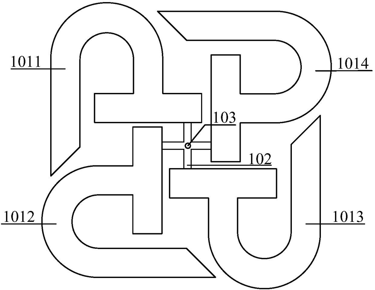
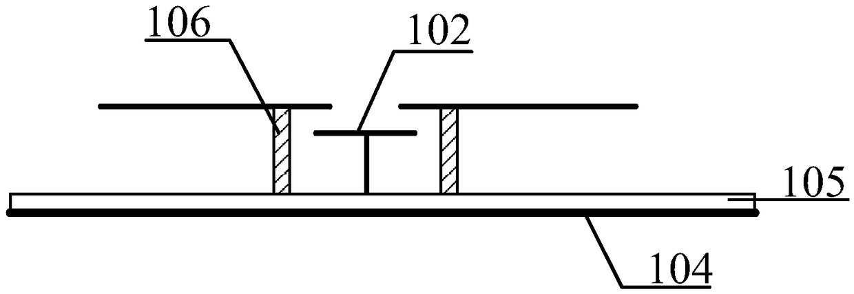
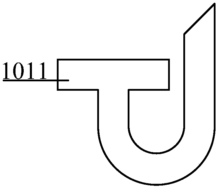
[0026] The antenna involved in the present invention mainly includes a dielectric substrate 105, a ground plane 104, four bent T-shaped radiating elements 1011, 1012, 1013 and 1014 (just an embodiment of the present invention) arranged above the dielectric substrate. Shaped probe 102 and foam column 106. Four bent T-shaped radiating elements and multiple L-shaped probes are indirectly fed through slot coupling. The bent T-shaped radiating element is rotated counterclockwise to achieve a miniaturized design. The size and angle of the bending will affect the impedance of the designed antenna Matching and impedance bandwidth. By adjusting the size of each radiating element, the coupling between the four bent T-shaped radiating elements 1011, 1012, 1013 and 1014 and the multiple L-shaped probes and the gap between the four bent T-shaped radiating elements, the antenna can To achieve a good match, it can meet the design requirements of circular polarization. Therefore, the antenna...


PUM


Abstract

The invention discloses a bent T-shaped rotating structure based directional circularly polarized antenna, and belongs to the technical field of mechanical structure design. The directional circularlypolarized antenna comprises a dielectric substrate, four bent T-shaped radiation units disposed above the dielectric substrate, a multi-L-shaped disposed under the radiation units and for coupled feeding, a ground plane disposed under the dielectric substrate, and four foam columns supporting the four bent T-shaped radiation units; and the lower end of the multi-L-shaped probe is connected to aninner conductor of a connector by coaxial feeding, and an outer conductor of the connector is connected with the ground plane. The invention relates to a bent T-shaped rotating structure based directional circularly polarized antenna, which adopts the multi-L-shaped probe feeding structure, a plurality of bent T-shaped radiating units, and the foam columns supporting radiation patches, effectivelyachieves circular polarization, directionality and miniaturization.

Description

Technical field [0001] The invention belongs to the technical field of mechanical structure design, and specifically relates to a directional circularly polarized antenna based on a bent T-shaped rotating structure. Background technique [0002] With the rapid development of the mobile communications industry worldwide, it has brought convenience and speed to our daily lives. People's requirements for mobile communications are not limited to the transmission of voice signals. The requirements for multimedia signals such as data, images, animation, and video are becoming more and more urgent, and the requirements for signal transmission quality are getting higher and higher. With the development of space technology and communications, circular polarization antennas play an important role in the wireless field with their strong advantages. Linearly polarized waves are prone to attenuation due to polarization deflection in the transmission environment, circularly polarized waves wi...

Claims


Application Information

Patent Timeline
Patent Type & Authority Applications(China)
IPC IPC(8): H01Q1/12H01Q1/36H01Q1/50
Inventor 李迎松董玥
Owner HARBIN ENG UNIV
Learn More