
Novel motor rotor structure

A motor rotor and rotor technology, applied in the direction of magnetic circuit shape/style/structure, magnetic circuit rotating parts, etc., can solve the problem of dislocation movement of silicon steel sheets, and achieve the effect of solving dislocation movement

Pending Publication Date: 2018-09-04
SUZHOU BETTER TECH
View PDF0 Cites 3 Cited by
  • Summary
  • Abstract
  • Description
  • Claims
  • Application Information

AI Technical Summary

Problems solved by technology

[0007] The present invention aims to provide a new type of motor rotor structure, which can solve the problem of misalignment and movement of silicon steel sheets during handling and transportation

Method used


Image

  • Novel motor rotor structure
  • Novel motor rotor structure
  • Novel motor rotor structure

Examples


Embodiment Construction

[0019] The following will clearly and completely describe the technical solutions in the embodiments of the present invention with reference to the accompanying drawings in the embodiments of the present invention. Obviously, the described embodiments are only some, not all, embodiments of the present invention. Based on the embodiments of the present invention, all other embodiments obtained by persons of ordinary skill in the art without making creative efforts belong to the protection scope of the present invention.

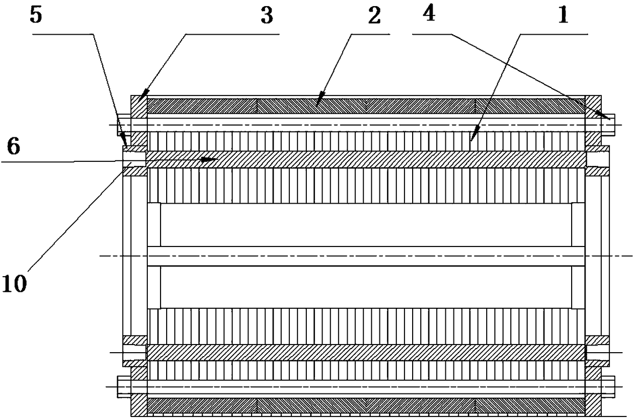
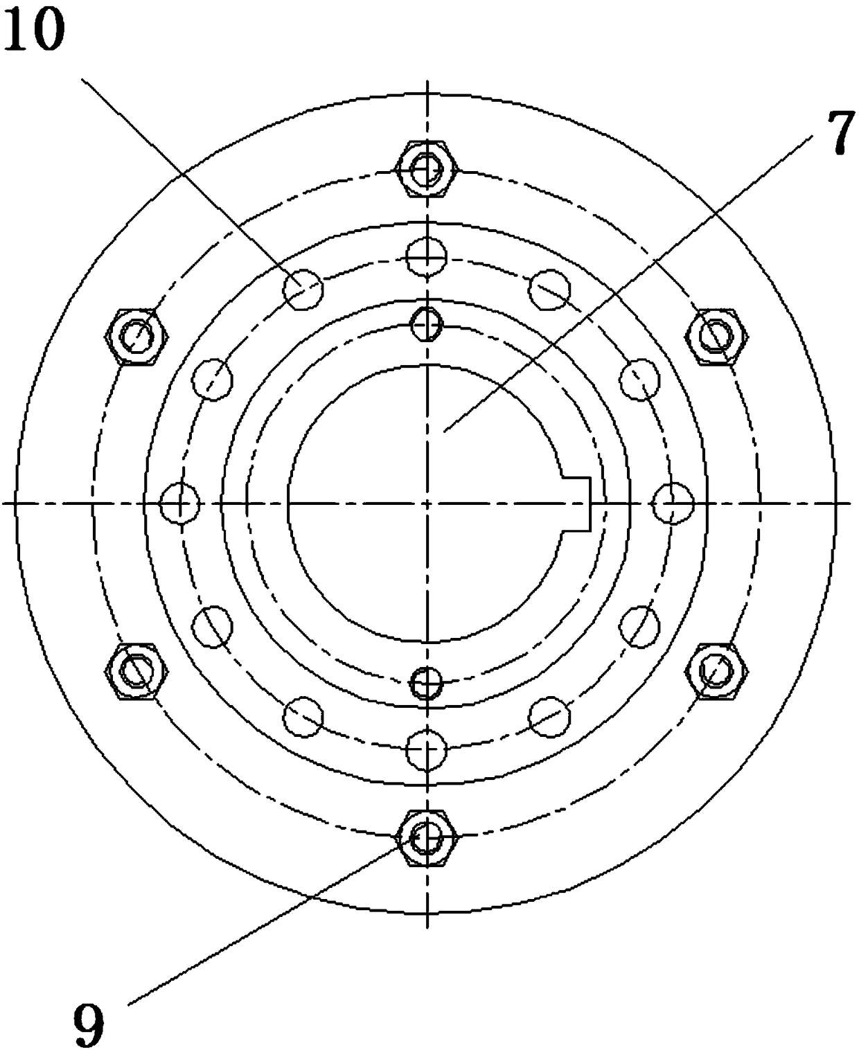
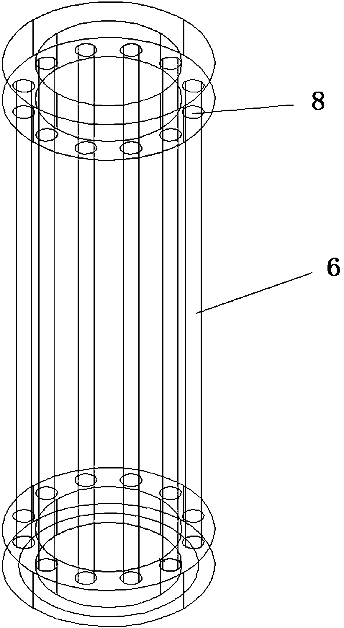
[0020] like Figure 1 to Figure 3 As shown, it is a new type of motor rotor structure according to the present invention, which is characterized in that it includes: rotor punching plate 1, magnetic steel 2, rotor magnetic steel pressure plate 3, fastening bolt 4 and locking mechanism, wherein the locking The mechanism includes an integrally formed cast aluminum end ring 5 and a squirrel cage bar 6, the cast aluminum end ring 5 is a circular ring, and a dynami...


PUM


Abstract

The invention discloses a novel motor rotor structure. The novel motor rotor structure comprises rotor punching pieces, magnetic steel, rotor magnetic steel pressure plates, fastening bolts and a locking mechanism, wherein the locking mechanism comprises aluminum-casting end rings and mouse cage strips which are integrally formed, each aluminum-casting end ring is a round ring, and movable balancing holes are formed in the round ring; the magnetic steel is mounted on outer arc surfaces of the rotor punching pieces, the rotor magnetic steel pressure plates are respectively arranged on two sidesof the rotor punching pieces, and one aluminum-casting end ring is arranged on the inner side of each rotor magnetic steel pressure plate; a plurality of bolt holes and a plurality of mouse cage holes are formed in the rotor magnetic steel pressure plates and the rotor punching pieces; the fastening bolts penetrate through the rotor magnetic steel pressure plates and the rotor punching pieces andare used for locking the rotor magnetic steel pressure plates and preventing the axial movement of the magnetic steel; and the mouse cage strips and the aluminum-casting end rings are connected withthe rotor punching pieces through interference fit. According to the novel motor rotor structure, the problems that silicon steel sheets are staggered and moved in the carrying and transportation processes can be solved.

Description

technical field [0001] The invention relates to the technical field of motors, in particular to a novel motor rotor structure, which is mainly suitable for speed-regulating permanent magnet synchronous motors. Background technique [0002] Since most of the motor rotors used in compressors do not have shafts during transportation, the rotor silicon steel sheets must be axially fixed after lamination. In the prior art, the rotor of the speed-regulating permanent magnet synchronous motor is generally locked axially by bolts, but the bolt holes and bolt tolerances must be properly matched, neither too tight nor too loose; Silicon steel sheets with large gaps are easy to dislocate and move. Moreover, in the process of handling and transportation, the slight collision of the rotor may also easily cause the dislocation and movement of the silicon steel sheet. [0003] The harm caused by dislocation movement is as follows: [0004] 1. Changes in the inner diameter and outer diam...

Claims


Application Information

Patent Timeline
Patent Type & Authority Applications(China)
IPC IPC(8): H02K1/27H02K1/28
CPCH02K1/27H02K1/28
Inventor 洪茂钦杜海洋余浩蔡泽农冯威
Owner SUZHOU BETTER TECH
Learn More