Slab continuous casting crystallizer flow field control method

A slab continuous casting and control method technology, which is applied in the field of slab continuous casting mold control, can solve problems such as inability to effectively improve the flow field state of the mold, excessive local flow velocity, and partial flow, etc., and achieve an improvement in the flow field of the mold , the effect of improving the quality

Active Publication Date: 2018-09-07
BAOSHAN IRON & STEEL CO LTD
View PDF19 Cites 21 Cited by
  • Summary
  • Abstract
  • Description
  • Claims
  • Application Information

AI Technical Summary

Problems solved by technology

For example, in the process of continuous casting, there is often a phenomenon of bias flow, that is, the flow rate of molten steel on both sides of the nozzle is quite different, resulting in a phenomenon that the flow rate on one side is faster and the other side is slower
Similarly, near the meniscus, local flow velocity is too fast or eddy currents are prone to occur.
Therefore, for such a complex flow field, the use of a single simple electromagnetic technology cannot effectively improve the flow field state of the mold, and more advanced flow field control devices and methods are needed

Method used


Image

  • Slab continuous casting crystallizer flow field control method
  • Slab continuous casting crystallizer flow field control method
  • Slab continuous casting crystallizer flow field control method

Examples


Embodiment

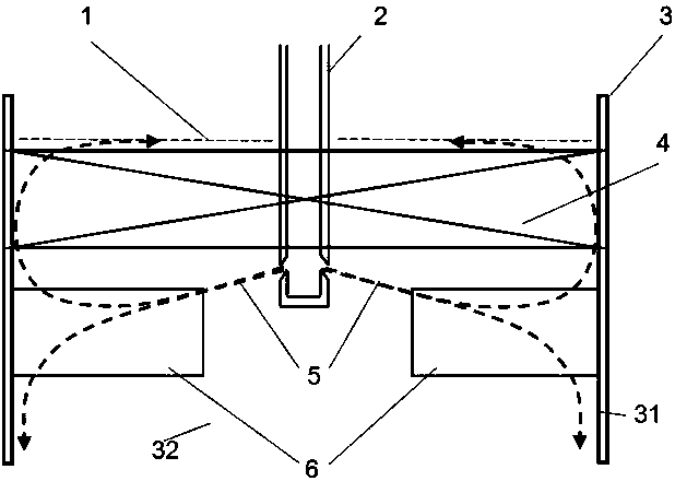
[0029]Production conditions: Production of IF steel plates with a casting speed of 1.6m / s, a width of 1450mm, and a thickness of 230mm. The insertion depth of the nozzle (that is, the distance from the meniscus to the upper edge of the nozzle) is 190mm. For such working conditions, the method of the present invention is used to simultaneously use an electromagnetic stirring device and an electromagnetic braking device, that is, an electromagnetic stirring device is used on the upper part of the crystallizer, and an electromagnetic braking device is used on the lower part.

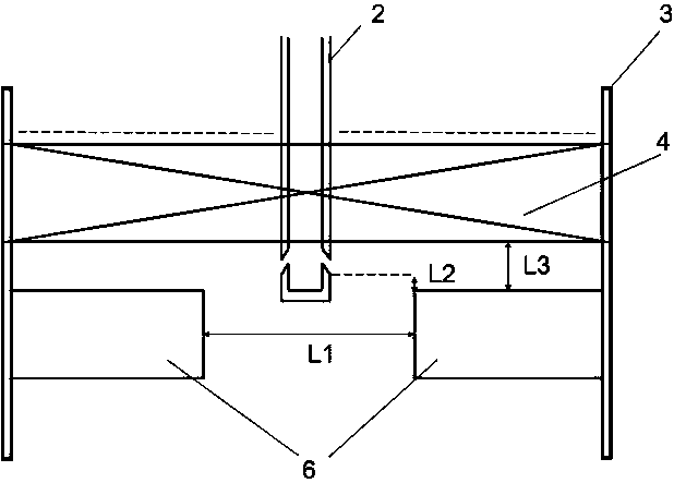
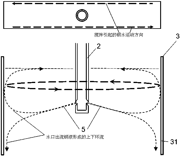
[0030] On one side of the wide surface of the crystallizer, the iron core height of the electromagnetic stirring device 4 installed on the upper part is 150mm, and the installation position is between the upper edge of the nozzle outlet and the meniscus, and the coverage ratio of the effective stirring area is greater than 0.75. Two electromagnetic brake devices 6 are installed in the lower part as a group, ...


PUM

PropertyMeasurementUnit
frequencyaaaaaaaaaa

Abstract

The invention discloses a slab continuous casting crystallizer flow field control method. The slab continuous casting crystallizer flow field control method comprises the following steps that electromagnetic stirring devices and electromagnetic braking devices are used for controlling a slab continuous casting crystallizer flow field, the electromagnetic stirring devices are configured at the upper parts of the two sides of a crystallizer wide surface, the electromagnetic braking devices are configured at the lower parts of the two sides of the crystallizer wide surface, and the electromagnetic stirring devices at the upper parts and the electromagnetic braking devices at the lower parts are mutually independent; the electromagnetic stirring devices at the upper parts are installed betweena space above the upper edge of the outlet of a water gap, and a meniscus surface, and the electromagnetic braking devices at the lower parts adopt regional braking, are located at the positions, below the outlet of the water gap, of the two sides of the outlet of the water gap, and act on an area, where water gap outflow streams flow through, between the water gap and a crystallizer narrow surface; and the electromagnetic stirring devices at the upper parts and the electromagnetic braking devices at the lower parts are correspondingly powered through two sets of power supplies, and correspondingly and independently control the current intensity. The electromagnetic stirring devices at the upper parts adopt a traveling wave magnetic field mode, and correspondingly drive liquid steel to make relative horizontal motion in magnetic fields on the two sides of the crystallizer wide surface.

Description

technical field [0001] The invention relates to a slab continuous casting mold control technology, in particular to a method for controlling the flow field of the slab continuous casting mold by using electromagnetic equipment. Background technique [0002] In the slab continuous casting process, in addition to the purity of the molten steel itself, the mold flow field will also greatly affect the quality of the continuous casting slab, especially the surface quality of the continuous casting slab. To judge the quality of the crystallizer flow field, the main considerations are whether slag roll is caused during the flow of molten steel, whether the initial solidification shell of continuous casting is uniform, and the impact of steel flow is too deep (inclusions in molten steel are not easy to float up and stay in the slab), etc. . The most effective way to control the flow field of the mold is electromagnetic stirring or electromagnetic braking. Electromagnetic stirring c...

Claims


Application Information

Patent Timeline
Patent Type & Authority Applications(China)
IPC IPC(8): B22D11/115B22D11/18
CPCB22D11/115B22D11/18
Inventor 吴存有周月明高齐金小礼章建雄陈臣刘国强
Owner BAOSHAN IRON & STEEL CO LTD
Why Eureka
Try Eureka