Extensible dual-direction main shaft

A spindle and axial technology, which is applied in the field of lathes, can solve the problems of inability to extend the two-way spindle and the inability to collet, so as to improve the service life, reduce the cost of replacement and maintenance, and improve the scope of application.

Active Publication Date: 2018-09-07
台州屹捷数控机床股份有限公司
View PDF7 Cites 2 Cited by
  • Summary
  • Abstract
  • Description
  • Claims
  • Application Information

AI Technical Summary

Problems solved by technology

[0007] The purpose of the present invention is to provide an extendable two-way spindle, which solves the problem that the collet of the two-way spindle cannot be extended

Method used


Image

  • Extensible dual-direction main shaft
  • Extensible dual-direction main shaft
  • Extensible dual-direction main shaft

Examples


Embodiment 1

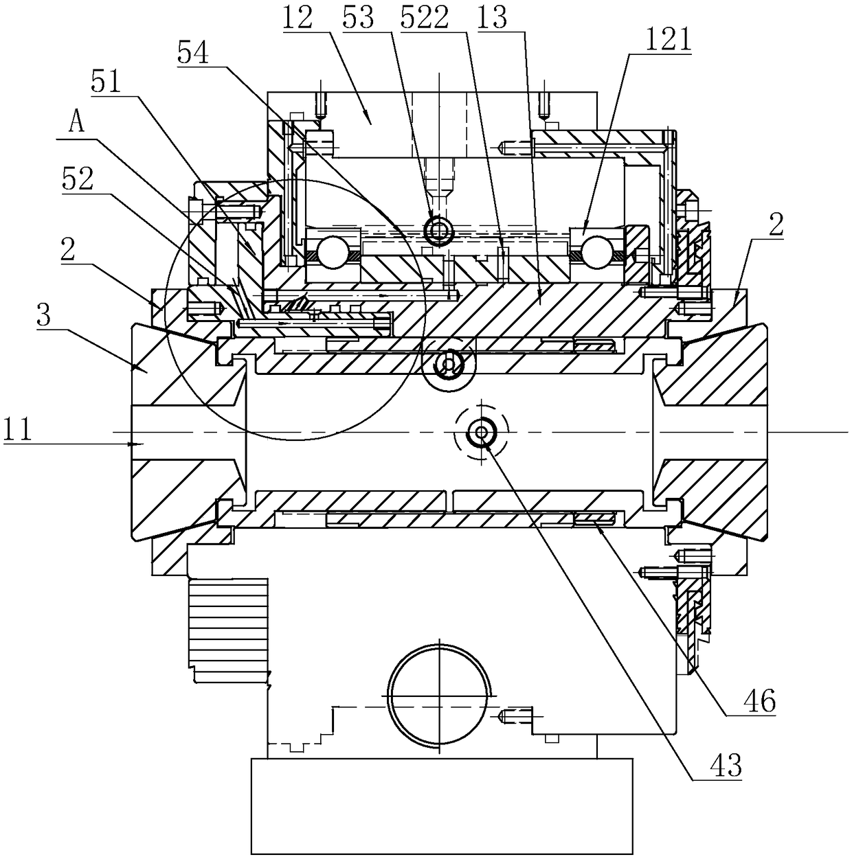
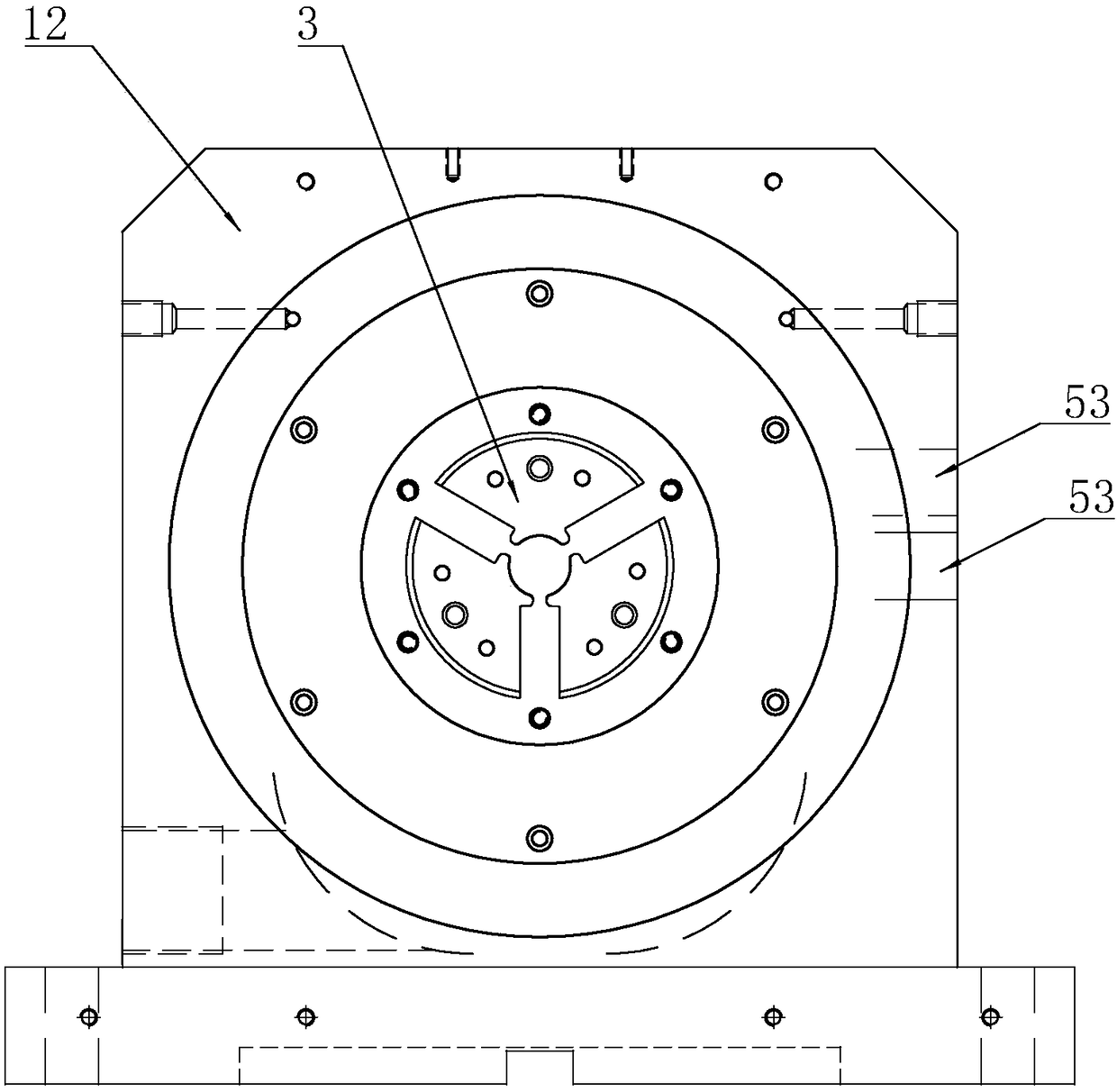
[0039] Example 1: An extendable bi-directional spindle such as figure 1 with image 3 As shown, it includes a shell assembly 1 with a through hole 11, two extension sleeves 2, two ferrules 3 embedded in the extension sleeves 2 for clamping workpieces, a pull sleeve 4 connecting two ferrules 3 and A control structure 5 that drives one of the extension sleeves 2 to move axially. When the extension sleeve 2 moves axially, the two ferrules 3 are forced to shrink.

[0040] The shell assembly 1 includes a box body 12 and a seat cover 13 . The seat cover 13 is arranged in the box body 12 and an angular contact bearing 121 is connected between the box body 12 and the box body 12 .

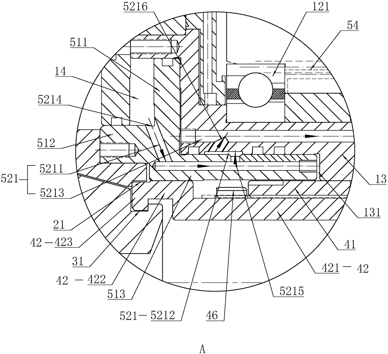
[0041] refer to figure 1 with figure 2 , the control structure 5 includes a piston sliding sleeve 51 controlled by hydraulic pressure, a corresponding oil pressure channel 52 and an external oil pump. An outer oil passage 53 communicating with the oil pressure passage 52 is arranged inside the box b...

Embodiment 2

[0049] Embodiment 2: as Figure 4 As shown, the difference from Embodiment 1 is that the structure of the pull sleeve 4 is different. The pull sleeve 4 includes a left sleeve 44 and a right sleeve 45 with hooks 423 on both ends facing away from each other. The hooks 423 are snapped into the limiting groove 31, and the outer wall of the left sleeve 44 is tightly embedded in the inner wall of the through hole 11. The inner wall of the left sleeve 44 is provided with an accommodating groove 441, and the right sleeve 45 also includes an extension part 421 threadedly connected with the accommodating groove 441 and an external connection part 422 tightly embedded in the inner wall of the through hole 11, and the hook part 423 is arranged on the external connection part 422 On the inner wall; between the outer connecting portion 422 and the left sleeve 44 is provided a locking piece 46 which is threadedly connected to the extension portion 421 and abuts against the left sleeve 44 .


PUM


Abstract

The invention discloses an extensible dual-direction main shaft which comprises a shell sleeve assembly with a through hole, two extension sleeves detachably fixed to the two ends of the shell sleeveassembly and clamping sleeves embedded in the extension sleeves for clamping workpieces. The circumferential surfaces of the clamping sleeves are inclined faces and abut against the inner walls of theextension sleeves, the circumferential end faces of the sides, in the through hole, of the clamping sleeves are provided with limiting grooves in a concaved mode, a pull sleeve with the two ends clamped into the limiting grooves and capable of being spirally stretched or locked is embedded in the through hole, and the shell sleeve assembly is provided with control structure which drives one extensions sleeve to move in the axial direction. The main shaft has the advantages that the clamping specifications of the dual-direction main shaft are changed on the condition of only changing some parts, the replacing cost and maintenance cost of the main shaft are greatly reduced, and the application range of the main shaft is effectively enlarged.

Description

technical field [0001] The invention relates to the field of lathes, in particular to an extendable bidirectional spindle. Background technique [0002] The double-head lathe is one of the most widely used lathes in machinery manufacturing and assembly factories. The difference from traditional lathes is that it can simultaneously perform product turning on both sides of the workpiece. [0003] A kind of numerically controlled double-head lathe disclosed by the Chinese patent whose authorization publication number is CN105665749A. [0004] Compared with traditional machine tools, the function of double-head turning is mainly realized by the bidirectional spindle that can be clamped in the middle of the workpiece. [0005] For example, the Chinese patent whose authorization publication number is CN105014451A discloses a wedge-push type double-headed car bidirectional spindle chuck, including a main shaft, a retaining ring, a wedge push ring, a spacer ring, jaws and a spring....

Claims


Application Information

Patent Timeline
Patent Type & Authority Applications(China)
IPC IPC(8): B23B19/02
Inventor 张瑜
Owner 台州屹捷数控机床股份有限公司
Why Eureka
Try Eureka