
Pneumatic layout of forward swept wing wide-body high subsonic aircraft adopting leading edge support wings

An aerodynamic layout and support wing technology, applied in the direction of wings, aircraft parts, heat reduction structures, etc., can solve the problems of increasing aircraft resistance, reducing wing lift, and destroying flight quality, so as to reduce waste resistance and induced resistance, enhance Effects on wing stiffness, increased aerodynamic efficiency and aircraft volume

Inactive Publication Date: 2018-09-07
BEIHANG UNIV
View PDF4 Cites 5 Cited by
  • Summary
  • Abstract
  • Description
  • Claims
  • Application Information

AI Technical Summary

Problems solved by technology

The shock wave increases the drag of the aircraft, reduces the lift of the wing, and also destroys the flight quality. The current traditional support wing layout cannot avoid this problem

Method used


Image

  • Pneumatic layout of forward swept wing wide-body high subsonic aircraft adopting leading edge support wings
  • Pneumatic layout of forward swept wing wide-body high subsonic aircraft adopting leading edge support wings
  • Pneumatic layout of forward swept wing wide-body high subsonic aircraft adopting leading edge support wings

Examples


Embodiment 1

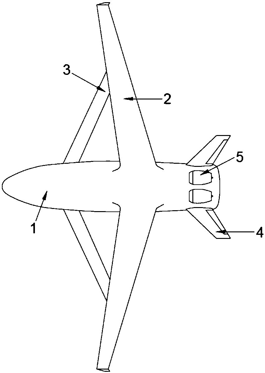
[0033] Example 1: The airfoils of the main wing 2 and the supporting wing 3 are RAE2822, the incoming flow Mach number is 0.75, and the flow Reynolds number is 1.66×10 7 . The horizontal distance s between the section of the main wing 2 and the section of the supporting wing 3 is the flow pressure cloud diagram when the chord length of the main wing 2 is taken as 0.8, 0, and -0.4 times respectively, as shown in Figure 6 , 7 , 8, in the figure, c is the chord length of the main wing, and x / c is the relative position of the main wing 2 in the horizontal direction, such as: x / c=-0.9 is 0.9 times of the main wing 2 chord length in front of the main wing 2 Location. Similarly z / c is the relative position of the main wing 2 in the vertical direction. It can be seen that compared with the same flow conditions, compared with the horizontal distance (s) of -0.4 and 0 times the chord length of the main wing, the shock wave interference area with a horizontal distance of 0.8 times th...

Embodiment 2

[0034] Example 2: The airfoil of the main wing 2 and the supporting wing 3 is RAE2822, the Mach number of the incoming flow is 0.75, and the Reynolds number of the flow is 1.66×10 7 . When the vertical distance g between the section of the main wing 2 and the section of the supporting wing 3 is taken as 0.2, 0.65, and 1 times the chord length of the main wing 2, respectively, the change curve of the overall lift-drag ratio with the horizontal distance s of the leading edge support and the trailing edge support is as follows: Figure 9 , 10 As shown, it can be seen that when the supporting wing 3 is in front of the main wing 2 to form a leading edge support, when the horizontal distance s is greater than or equal to 1.0 times the chord length of the main wing 2, the lift-to-drag ratio is very close to the undisturbed lift-to-drag ratio. When the supporting wing 3 is behind the main wing 2 to form a trailing edge support, the absolute value of the horizontal distance s must be ...


PUM


Abstract

The invention relates to a pneumatic layout of a wide-body high subsonic aircraft adopting leading edge support wings. The support wings are arranged at a certain distance below the fronts of main wings so as to form leading edge support, and a design of the front swept main wings and a wide-body fuselage is adopted; the relative position of the leading edge support wings and the main wings and the forward swept arrangement form of the main wings are rationally designed; the main wing adopts a way of arranging upper single wings upsidedown at the lower part, and have forward sweep angles. Thesupport wings adopt a way of arranging lower single wings upsidedown at the upper part, and have backward sweep angles; the tips of the support wings are connected with the lower surfaces of the tip parts of the main wings, and less overlap only exists at the joint positions of the tip parts of the support wings and the main wings. By adopting the pneumatic layout of the wide-body high subsonic aircraft adopting the leading edge support wings, waste resistance and induced drag are reduced, and the aerodynamic efficiency and volume of the aircraft are increased; the traditional arrangement formof placing the support wings under the main wings is changed into arranging the supporting wings in front, so that the overlooked overlapping area of the support wings and the main wings is minimized, and the defect that shock waves are formed due to too early layout of the traditional support wings can be avoided.

Description

technical field [0001] The invention belongs to the technical field of aircraft aerodynamic layout design, and in particular relates to an aerodynamic layout of a wide-body high subsonic aircraft adopting leading edge support wings. Background technique [0002] High subsonic jet passenger aircraft (transport aircraft) has become one of the main means of transportation in the world, and improving the aerodynamic efficiency of high subsonic jet aircraft can obtain huge economic and military benefits. In February 2016, Lockheed Martin completed the wind tunnel test of the new wide-body hybrid wing-body (HWB) layout. The results showed that the HWB layout has the characteristics of high aerodynamic efficiency and short take-off and landing distance. Therefore, the HWB layout is a reasonable layout choice for future large-scale high subsonic aircraft. [0003] Increasing the aspect ratio of the wing is an important way to improve the aerodynamic efficiency. Increasing the wing...

Claims


Application Information

Patent Timeline
Patent Type & Authority Applications(China)
IPC IPC(8): B64C3/00B64C3/36B64C1/00
CPCB64C1/00B64C3/00B64C3/36
Inventor 卓梅芳蒋崇文李志豪林宏渊高振勋
Owner BEIHANG UNIV
Learn More