
A high-efficiency non-stick filter cake feeder

A feeder and sticky material technology, applied in the field of high-efficiency non-stick material filter cake feeder, can solve the problems of filter cake feeder motor load increase, jamming, serious problems, etc., to ensure synchronization and stability , Reducing the resistance load, and the effect of ingenious structural design

Active Publication Date: 2019-02-01
JIANGSU A BITION ENVIRONMENTAL EQUIP
View PDF7 Cites 0 Cited by
  • Summary
  • Abstract
  • Description
  • Claims
  • Application Information

AI Technical Summary

Problems solved by technology

[0005] The whole plate structure scraper, for materials with low viscosity and high water content, due to the whole plate scraping, the scraping volume is large, the material processing capacity is large, and the efficiency of conveying materials is high; but for the viscous materials, the filtering The impeller blades of the valve body of the cake feeder are easily adhered by the material, and accumulate thicker and become hard
The full-plate scraper has a large contact area with the wet material, and the bonding area is also large, making it more difficult to handle
Over time, it is difficult for the internal scraper to clean it, and the load resistance of the entire scraper gradually increases, causing more serious wear on the scraper
More seriously, it will lead to an increase in the motor load of the filter cake feeder, resulting in high current and stuck problems of the equipment

Method used


Image

  • A high-efficiency non-stick filter cake feeder
  • A high-efficiency non-stick filter cake feeder
  • A high-efficiency non-stick filter cake feeder

Examples


Embodiment Construction

[0028] The content of the present invention will be further described in detail below in conjunction with the accompanying drawings.

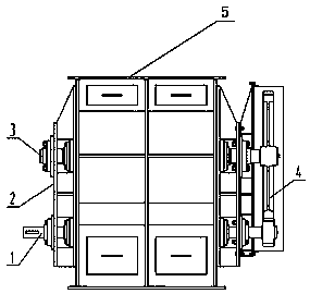
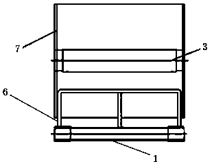
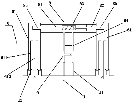
[0029] Such as figure 1 with 2 As shown, a high-efficiency non-stick filter cake feeder includes a casing 5, a driving shaft 1, a driven shaft 3, meshing gears 4, and a rotary valve body impeller 7. The driving shaft 1 and the driven shaft 3 are installed on the casing 5 through the support base 2 , and the driven shaft 3 and the driving shaft 1 are respectively installed on the upper and lower sides of the casing 5 in parallel. The driven shaft 3 and the driving shaft 1 are connected through a meshing gear 4 . The rotary valve body impeller 7 is installed on the driven shaft 3 . The present invention also includes a scraping mechanism 6 . Such as image 3 As shown, the scraping mechanism 6 includes two side plates 61 and an overlapping mechanism 8 . Such as image 3 with 4 As shown, thread grooves 12 are provided on both ends of the dr...


PUM


Abstract

The invention discloses an efficient material-sticking-free filter cake feeding machine. The efficient material-sticking-free filter cake feeding machine comprises a machine shell, a driving shaft, adriven shaft, an engaging gear and a rotating valve body impeller; the driving shaft and the driven shaft are installed on the machine shell; the driving shaft and the driven shaft are connected through the engaging gear; the rotating valve body impeller is installed on the driven shaft; a material stripping mechanism is further included; the material stripping mechanism comprises two side platesand one overlap joint mechanism; the upper sides of the two ends of the driving shaft are provided with threaded grooves; the lower ends of the side plates are provided with threaded columns; the sideplates are connected in the threaded grooves of the driving shaft through the threaded columns; the overlap joint mechanism is movably installed between the upper ends of the two side plates; and theouter side faces of the two side plates are attached to the inner side face of the rotating valve body impeller. According to the efficient material-sticking-free filter cake feeding machine, the material stripping mechanism is formed by movably connecting the two side plates and the overlap joint mechanism, the side plates and the driving shaft are movably connected, the overlap joint mechanismand the two side plates are movably connected, and in this way, the material stripping mechanism is very convenient to install and replace.

Description

technical field [0001] The invention relates to a high-efficiency non-stick filter cake feeder, in particular to a scraping mechanism of the feeder. Background technique [0002] The filter cake feeder is a volumetric quantitative feeder, and the feeding amount can be adjusted and controlled within a certain range through frequency conversion speed regulation. It is composed of valve body, transmission shaft, vane and motor reducer. The geared motor drives the transmission shaft and the impeller to rotate, so as to achieve the purpose of ash unloading and feeding. The device is suitable for powder materials, has the effect of locking air, and is especially suitable for the feeding of low-pressure pneumatic conveying devices. It has the characteristics of good blade wear resistance, high air-locking performance, thorough discharge, stable connection, and compact structure. The elastic impeller feeder adopts an elastic rotor, which has better sealing performance and ensures ...

Claims


Application Information

Patent Timeline
Patent Type & Authority Patents(China)
IPC IPC(8): B65G29/00
CPCB65G29/00
Inventor 刘必红左其武张连中周峰
Owner JIANGSU A BITION ENVIRONMENTAL EQUIP
Learn More