Steel shot quenching device

A technology of quenching device and steel shot, applied in the direction of quenching device, furnace, heat treatment equipment, etc., can solve the problems of different quenching cooling speed, increase of water temperature in quenching pool, and high surface temperature of steel shot, and achieve little difference in metallographic structure, The effect of improving the quality and reducing the defect rate

Active Publication Date: 2019-09-03
CHONGQING QINGLAN MACHINERY MFG
View PDF7 Cites 0 Cited by
  • Summary
  • Abstract
  • Description
  • Claims
  • Application Information

AI Technical Summary

Problems solved by technology

[0003] But above-mentioned steel shot quenching device has following shortcoming: 1, because the collection mechanism of quenching pool is the recovery trolley, just can carry out when centrifuge stops working, therefore is unfavorable for continuous production; Drain the water in the quenching pool, thereby causing a waste of water resources; 3. The surface temperature of the steel shots thrown out by the centrifuge is relatively high, which causes the water temperature in the quenching pool to rise, and for the same batch of steel shots, The temperature of the quenching pool changes greatly, so that the cooling rate of quenching is different, and the performance of the steel shot is relatively different, resulting in more defective products

Method used


Image

  • Steel shot quenching device
  • Steel shot quenching device
  • Steel shot quenching device

Examples


Embodiment 1

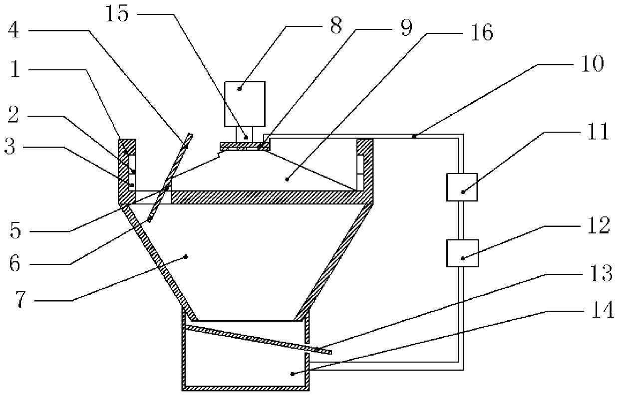
[0024] Example 1, such as figure 1 Shown: steel shot quenching device, including quenching pool 1, the shape of quenching pool 1 is circular, the center bottom of quenching pool 1 is connected with centrifuge 8 through active rotating shaft 15, centrifuge 8 is located above quenching pool 1, quenching pool The bottom surface of 1 is fixedly installed with an upwardly protruding round platform 16. The cross section of the round platform 16 is trapezoidal, and the round platform 16 adopts heat-resistant bricks to build, the structure is relatively stable, and high temperature resistant. The peripheral surface of the round platform 16 is hinged with a plurality of cover plates 4, the cover plates 4 are close to the edge part of the quenching pool 1, the cover plates 4 are distributed along the radial direction of the round platform 16, and the cover plates 4 are divided into water retaining parts with the hinge point as the center. Section and discharge section, wherein the water...

Embodiment 2

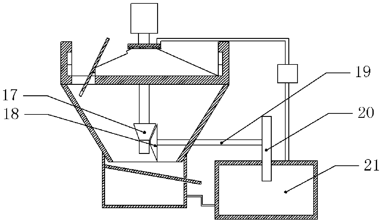
[0027] Embodiment 2, differs from Embodiment 1, such as figure 2 As shown, the driving shaft 15 at the end of the centrifuge 8 passes through the center of the round table 16 and extends into the funnel chamber 7. The free end of the driving shaft 15 is fixedly connected with a driving bevel gear 17, and the right side of the driving bevel gear 17 is meshed with a driven umbrella. Gear 18, driving bevel gear 17 is perpendicular to the central axis of driven bevel gear 18, and the free end of driven bevel gear 18 is equipped with passive rotating shaft 19, and driven bevel gear 18 is connected with cooling car 20 through passive rotating shaft 19, and cooling car 20 Located on the right side of the driven bevel gear 18. The right side of the water tank 14 is provided with a cooling pool 21, the cooling pool 21 communicates with the water tank 14, and the recovery pipe 10 communicates with the cooling pool 21, and the top of the cooling pool 21 is lower than the top of the wate...

Embodiment 3

[0028] Embodiment 3 is different from Embodiment 1 in that adjacent water outlet holes face each other and are inclined downward.

[0029] Embodiment 1, during actual application, refer to figure 1 , inject water with a temperature of about 20 degrees into the quenching pool 1, when the liquid level is at the top of the round platform 16, pour high-temperature molten steel into the centrifuge 8, start the centrifuge 8 and start to rotate, the role of molten steel in the centrifuge 8 Do centrifugal movement, and fall into the water in the quenching pool 1, and rapidly cool to form steel shots, and most of the steel shots are concentrated on the edge of the quenching pool 1. With the increase in the number of steel shots, the water temperature in the quenching pool 1 rises to about 40 degrees, reaching the critical point of the steel shot, where the temperature sensor receives the temperature change, and at the same time the self-recovery fuse under the action of temperature , ...


PUM


Abstract

The invention relates to the technical field of steel shot production, and discloses a steel shot quenching device, which includes a quenching pool, a centrifuge is rotatably connected to the middle of the quenching pool, a round table is arranged on the bottom of the quenching pool, and a plurality of cover plates are hinged on the edge of the round table. Including the water retaining section and the discharge section, the side of the round table close to the discharge section is provided with a discharge port, the discharge section and the round table are connected by springs; the inner wall of the quenching pool is equipped with a temperature control circuit and a magnet, the temperature control circuit is connected with the magnet, the centrifugal Electromechanical connection, the free end of the discharge section is provided with an iron sheet; the bottom of the quenching pool is provided with a funnel chamber and a cooling mechanism, the bottom of the funnel chamber is connected to a water tank, and the side wall of the water tank is provided with a discharge port, and the discharge port is equipped with a tilting device. And the net plate which is against the side wall of the water tank, the water tank and the round table are connected through a recovery pipe, and a water pump is installed on the recovery pipe. The present invention can solve the problem of large performance differences of the same batch of steel shot in the prior art, and improve the performance of the steel shot.

Description

technical field [0001] The invention relates to the technical field of steel shot production, in particular to a steel shot quenching device. Background technique [0002] Steel shot is a kind of spherical particle made of special material through special heat treatment. In the process of steel shot preparation, the equipment generally used is a centrifuge, which melts the high-carbon steel and pours it into a rotating centrifugal plate, and then relies on the centrifugal force of the centrifuge to throw out various sizes of shot bodies. The pellets will fall into the quenching pool for rapid cooling to form steel pellets. Generally, the quenching pool is relatively large, and when the accumulated volume of the steel shots thrown out by the centrifuge accounts for about two-thirds of the volume of the quenching pool, the centrifuge should be shut down for a period of time, and the water in the quenching pool should be drained first, and then the steel shots should be collec...

Claims


Application Information

Patent Timeline
Patent Type & Authority Patents(China)
IPC IPC(8): C21D9/36C21D1/63B22F9/10
CPCB22F9/10C21D1/63C21D9/36Y02P10/20
Inventor 苏亚君
Owner CHONGQING QINGLAN MACHINERY MFG
Why Eureka
Try Eureka