Steel shot quenching device
A technology of quenching device and steel shot, which is applied in the direction of quenching device, furnace type, furnace, etc., can solve the problems of different quenching cooling speed, rising water temperature of quenching pool, high surface temperature of steel shot, etc., and achieve little difference in metallographic structure, The effect of improving quality and reducing defect rate
- Summary
- Abstract
- Description
- Claims
- Application Information
AI Technical Summary
Problems solved by technology
Method used
Image
Examples
Embodiment 1
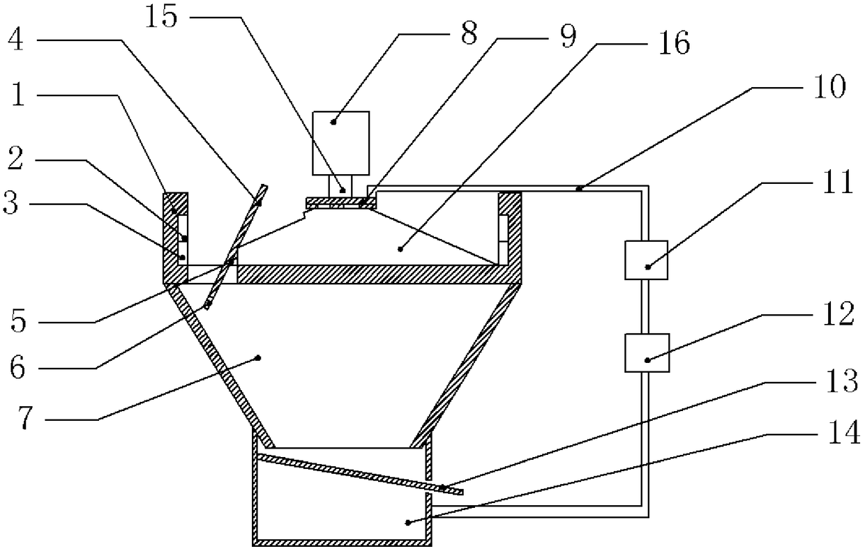
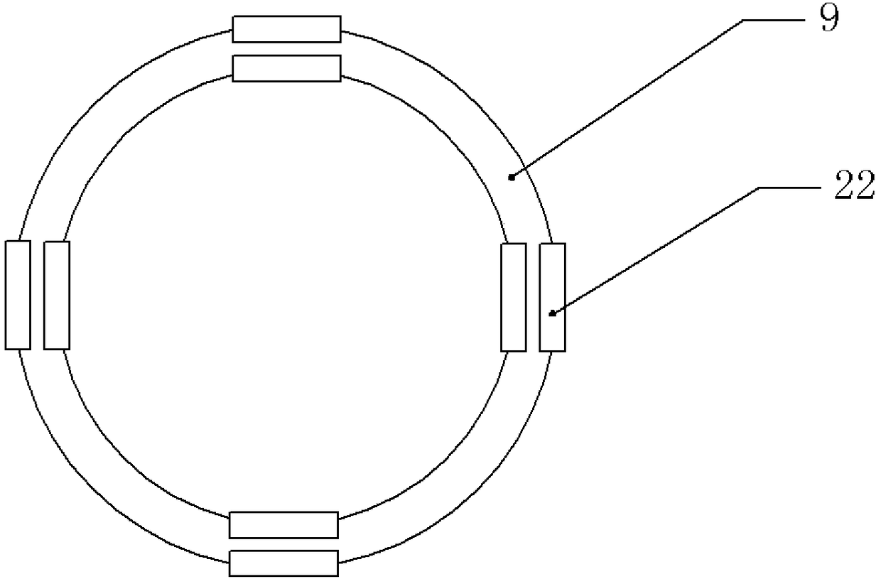
[0024] Example 1, such as figure 1 Shown: steel shot quenching device, including quenching pool 1, the shape of quenching pool 1 is circular, the center bottom of quenching pool 1 is connected with centrifuge 8 through active rotating shaft 15, centrifuge 8 is located above quenching pool 1, quenching pool The bottom surface of 1 is fixedly installed with an upwardly protruding round platform 16. The cross section of the round platform 16 is trapezoidal, and the round platform 16 adopts temperature-resistant bricks to build, the structure is relatively stable, and high temperature resistant. The peripheral surface of the round platform 16 is hinged with a plurality of cover plates 4, the cover plates 4 are close to the edge part of the quenching pool 1, the cover plates 4 are distributed along the radial direction of the round platform 16, and the cover plates 4 are divided into water-retaining parts centered on the hinge point. Section and discharge section, wherein the water...
Embodiment 2
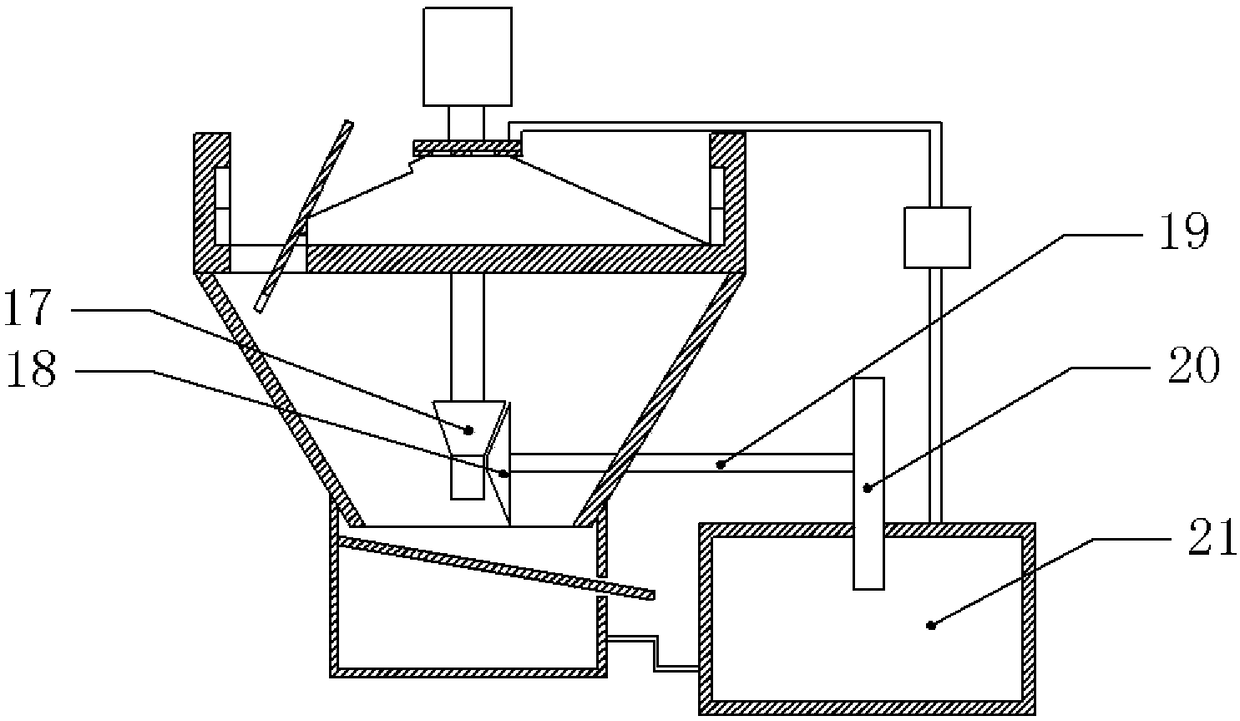
[0027] Embodiment 2, differs from Embodiment 1, such as figure 2 As shown, the driving shaft 15 at the end of the centrifuge 8 passes through the center of the round table 16 and extends into the funnel chamber 7. The free end of the driving shaft 15 is fixedly connected with a driving bevel gear 17, and the right side of the driving bevel gear 17 is meshed with a driven umbrella. Gear 18, driving bevel gear 17 is perpendicular to the central axis of driven bevel gear 18, and the free end of driven bevel gear 18 is equipped with passive rotating shaft 19, and driven bevel gear 18 is connected with cooling car 20 through passive rotating shaft 19, and cooling car 20 Located on the right side of the driven bevel gear 18. The right side of the water tank 14 is provided with a cooling pool 21, the cooling pool 21 communicates with the water tank 14, and the recovery pipe 10 communicates with the cooling pool 21, and the top of the cooling pool 21 is lower than the top of the wate...
Embodiment 3
[0028] Embodiment 3 is different from Embodiment 1 in that adjacent water outlet holes face each other and are inclined downward.
[0029] Embodiment 1, during actual application, refer to figure 1 , inject water with a temperature of about 20 degrees into the quenching pool 1, when the liquid level is at the top of the round platform 16, pour high-temperature molten steel into the centrifuge 8, start the centrifuge 8 and start to rotate, the role of molten steel in the centrifuge 8 Do centrifugal movement, and fall into the water in the quenching pool 1, and rapidly cool to form steel shots, and most of the steel shots are concentrated on the edge of the quenching pool 1. With the increase in the number of steel shots, the water temperature in the quenching pool 1 rises to about 40 degrees, reaching the critical point of the steel shot, where the temperature sensor receives the temperature change, and at the same time the self-recovery fuse under the action of temperature , ...
PUM
 Abstract
Description
Claims
Application Information
 - R&D
- Intellectual Property
- Life Sciences
- Materials
- Tech Scout
- Unparalleled Data Quality
- Higher Quality Content
- 60% Fewer Hallucinations
Browse by: Latest US Patents, China's latest patents, Technical Efficacy Thesaurus, Application Domain, Technology Topic, Popular Technical Reports.
© 2025 PatSnap. All rights reserved.Legal|Privacy policy|Modern Slavery Act Transparency Statement|Sitemap|About US| Contact US: help@patsnap.com


