A commercial electric fan blade

An electric fan and fan blade technology, which is applied to the components of the pumping device for elastic fluid, non-variable-capacity pumps, pump components, etc. The effect of noise reduction is obvious and the effect of reducing resistance

Active Publication Date: 2020-03-20
广东飞鹿电器有限公司
View PDF1 Cites 0 Cited by
  • Summary
  • Abstract
  • Description
  • Claims
  • Application Information

AI Technical Summary

Problems solved by technology

Due to the above-mentioned defects in the design of the fan blades of this structure, there are adverse phenomena such as insufficient air volume and high noise during the use of the fan blades.

Method used


Image

  • A commercial electric fan blade
  • A commercial electric fan blade
  • A commercial electric fan blade

Examples


no. 1 example

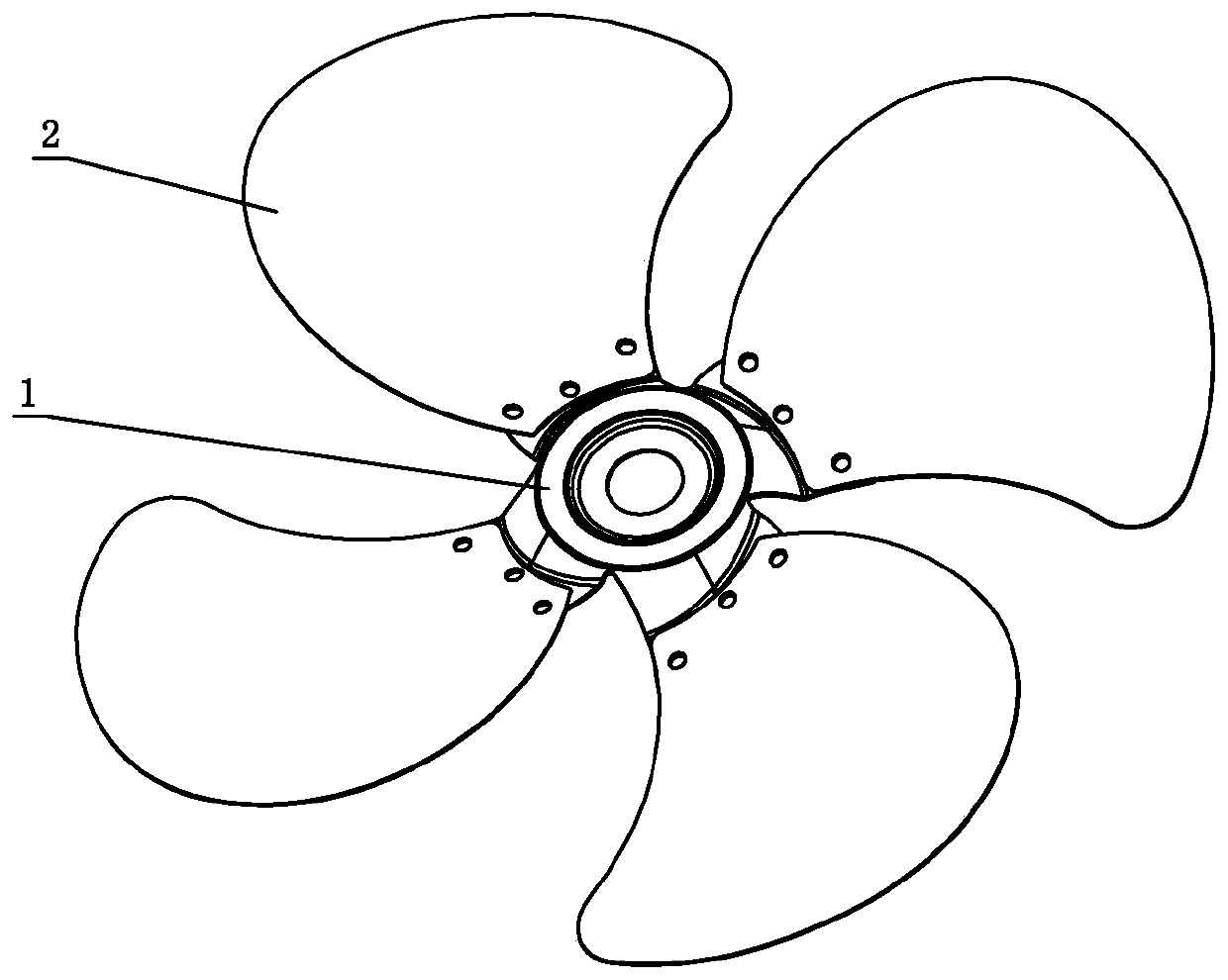
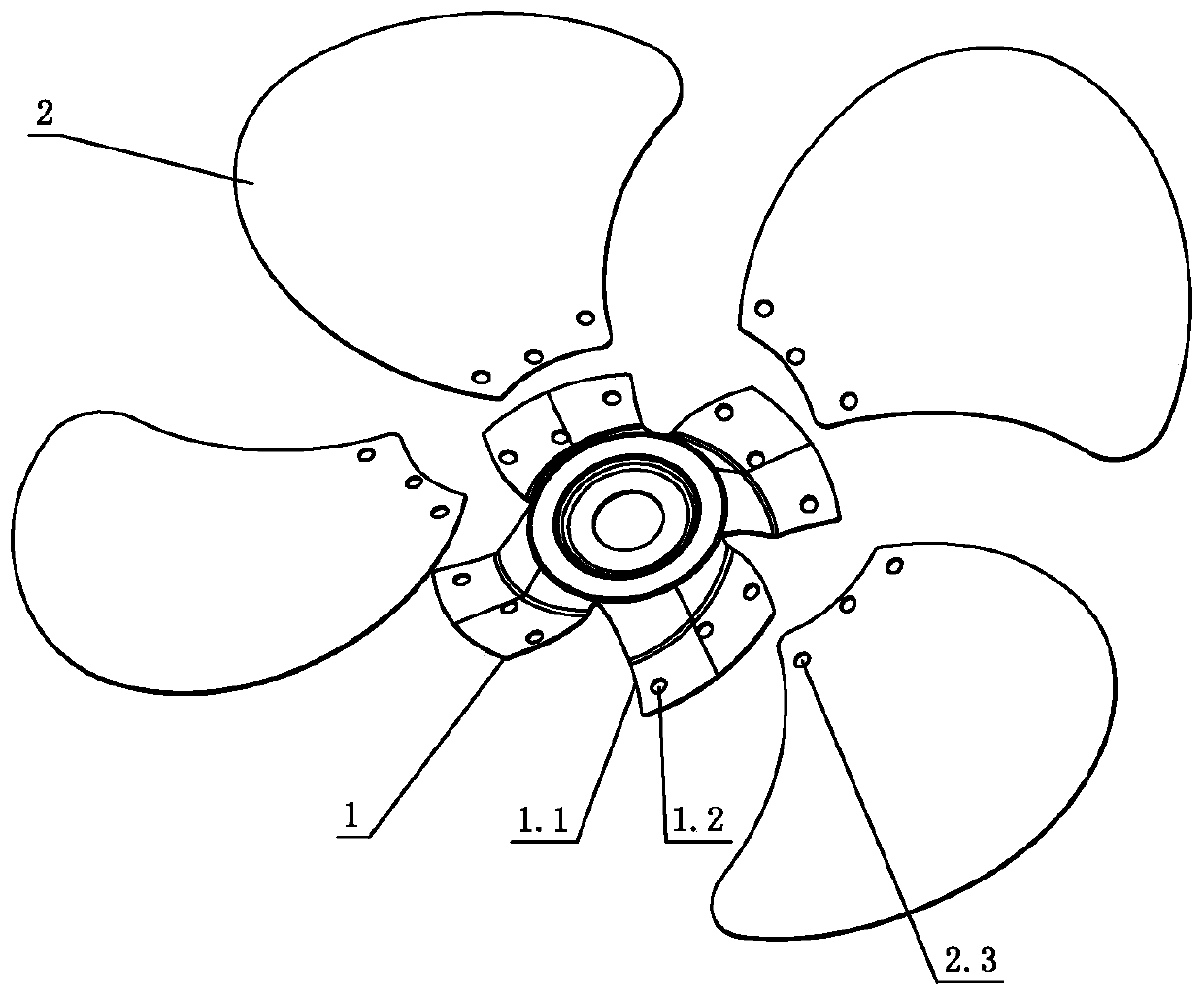
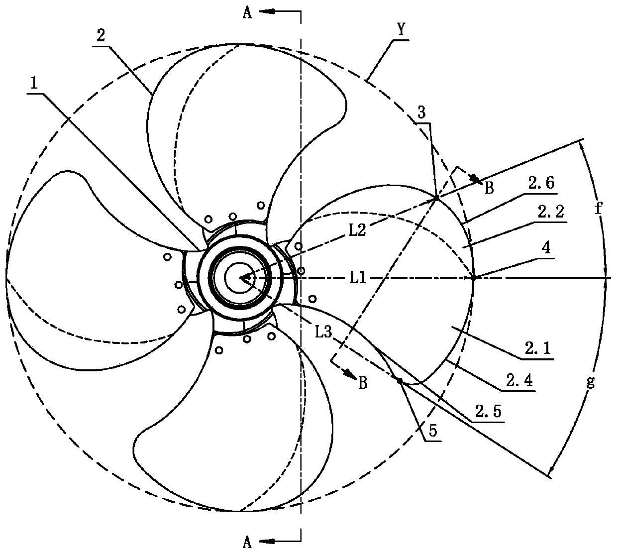
[0032] see Figure 1-Figure 5 The diameter of the commercial electric fan blade of the present embodiment is 16 inches, and the blade includes a hub 1 and four blades 2 arranged on the peripheral side of the hub 1, the root of the blade 2 is connected with the hub 1, and the blade 2 starts from the root Radially twisted and extended, each blade 2 is rotationally symmetrical and circularly distributed; the root of the blade 2 is inclined relative to the rotation axis of the hub 1, and the angle c between each other is 68°-88°; the blade 2 is twisted with a windward area 2.1 and a wind gathering area. Area 2.2, windward area 2.1 and wind gathering area 2.2 are arranged obliquely respectively, and the inclination angle e of wind gathering area 2.2 is greater than the inclination angle d of windward area 2.1, and wind gathering area 2.2 is located at the rear side of windward area 2.1, and the inclination angle of windward area 2.1 d is 5°-20°, and the inclination angle e of the w...

no. 2 example

[0041] see Figure 6-Figure 9 , the diameter of the commercial electric fan blade involved in this embodiment is 18 inches, and it is different from the first embodiment in that: in the same blade, the included angle c is 74°, the inclination angle d is 13°, and the inclination angle e is 34°; the hub 1 and the blade 2 are integrally injection molded by plastic, and the middle part of the hub 1 is formed with a spline structure 1.3.

[0042] Furthermore, the included angle f between the connecting line L1 and the connecting line L2 is 31°; the included angle g between the connecting line L1 and the connecting line L3 is 37°. in addition, Figure 7 The section line in the B'-B' direction is the section line passing through the wind gathering point 3 on the blade 2 and perpendicular to the connecting line L3.

[0043] Other parts not described are the same as those of the first embodiment, and will not be analyzed and described here.

no. 3 example

[0045] see Figure 10-Figure 13 , the diameter of the commercial electric fan blade involved in this embodiment is 20 inches, and it is different from the first embodiment in that: in the same blade, the included angle c is 78°, the inclination angle d is 10°, and the inclination angle e is 30°; the hub 1 and the blade 2 are integrally injection molded by plastic, and the middle part of the hub 1 is formed with a spline structure 1.3.

[0046] Furthermore, the included angle f between the connecting line L1 and the connecting line L2 is 21°; the included angle g between the connecting line L1 and the connecting line L3 is 40°. in addition, Figure 7 The section line in the B"-B" direction is the section line that passes through the wind gathering point 3 on the blade 2 and is perpendicular to the connecting line L3.

[0047] Other parts not described are the same as those of the first embodiment, and will not be analyzed and described here.


PUM


Abstract

The invention provides a commercial electric fan blade. Each commercial electric fan comprises a hub and four blades, wherein the roots of the blades are connected to the hub; the blades extend radially from the roots in a distorting manner, are in rotational symmetry and are distributed annually and uniformly; the roots of the blades are slantwise arranged relative to a rotating shaft of the hub;an included angle between the fan blades is 68 degrees to 88 degrees; a windward area and a wind gathering area are formed in each blade in a distorting manner and are respectively slantwise; the angle of tilt e of the wind gathering area is greater than the angle of tilt d of the windward area; and the wind gathering area is located at the rear side of the windward area. The commercial electricfan blade has the beneficial effects that the air output of the blades is greatly increased by about 20% under the effects of the windward area and the wind gathering area through the reasonable slantwise distortion; the decibel of noise is greatly reduced by about 20%-30%; the reasonable angles of tilt of the blades can reduce the collision effect of the blades and air on the basis of maintaininglarge wind volume, thus reducing resistance and motor load; and the reasonable distortion resistance of the blades prevents the blades from directly colliding with air to produce noise.

Description

technical field [0001] The invention relates to an electric fan, in particular to a commercial electric fan blade. Background technique [0002] In the electric fan industry, the design of the fan blades is related to the air volume and noise of the fan blades, so it is particularly important. Among them, the tilt and / or twist design of the blades in the fan blades is more important, but the existing blades on the market are generally not accurate. The inclination and / or twist control of the blades is simply designed to ensure that the wind is generated, resulting in small air volume and high noise during the operation of the blades, which affects the user's performance; in addition, the blades on the market are generally equipped with an odd number of blades , the fan blades of the even-numbered blades are relatively small. This is because the fan blades of the even-numbered blades have a larger amplitude, less air volume, and higher noise, which cannot achieve the best per...

Claims


Application Information

Patent Timeline
Patent Type & Authority Patents(China)
IPC IPC(8): F04D29/32F04D29/38F04D29/66
CPCF04D29/325F04D29/386F04D29/666
Inventor 梁文广
Owner 广东飞鹿电器有限公司
Why Eureka
Try Eureka