Braking torque loading device of digital control spiral bevel gear lapping machine and control method

A spiral bevel gear and braking torque technology, which is applied to the loading braking torque device and its control field of a CNC spiral bevel gear grinding machine, can solve the problems of multi-point grinding of machine tools, high-speed grinding obstacles of gear grinding machines, etc. The stability of the hydraulic motor is not high, and the maintenance and control are convenient, the grinding efficiency is improved, and the grinding effect is good.

Active Publication Date: 2010-01-27
通用技术集团天津第一机床有限公司
View PDF6 Cites 0 Cited by
  • Summary
  • Abstract
  • Description
  • Claims
  • Application Information

AI Technical Summary

Problems solved by technology

[0008] The loading and grinding of the prior art gear grinding machine has the following defects: due to the limitation of the hydraulic proportional valve, there are only two loading braking torques to choose from on the driving surface or the reverse surface. When there are many different braking torque values, this method cannot meet the needs of multi-point grinding of the machine tool; secondly, due to the low stability of the hydraulic motor, it hinders the high-speed grinding of the gear grinding machine; Combining together to control the adjustment of the grinding machine is very troublesome and prone to failure

Method used


Image

  • Braking torque loading device of digital control spiral bevel gear lapping machine and control method
  • Braking torque loading device of digital control spiral bevel gear lapping machine and control method
  • Braking torque loading device of digital control spiral bevel gear lapping machine and control method

Examples


Embodiment Construction

[0029] Embodiments of the present invention will be further described below in conjunction with the accompanying drawings.

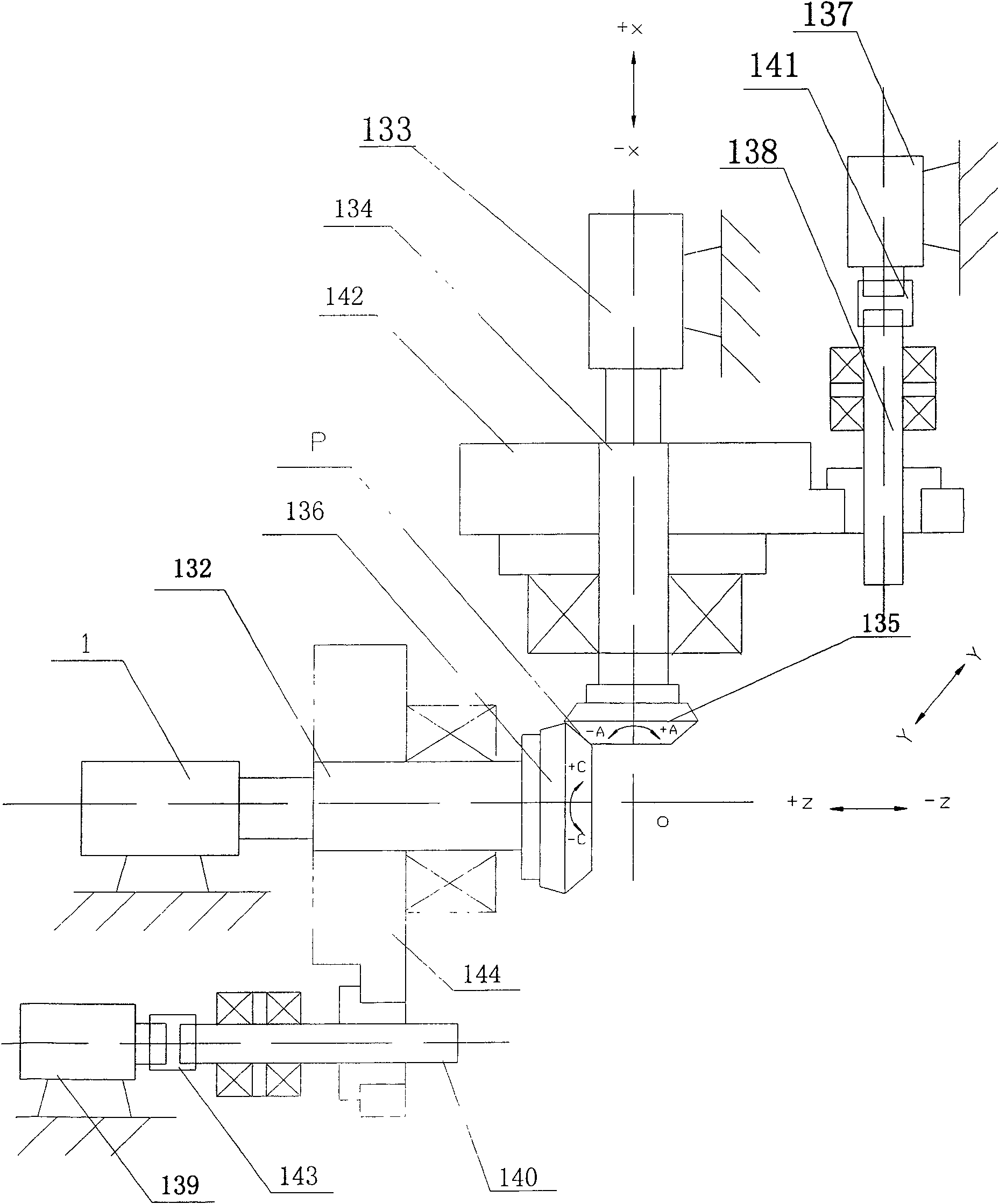
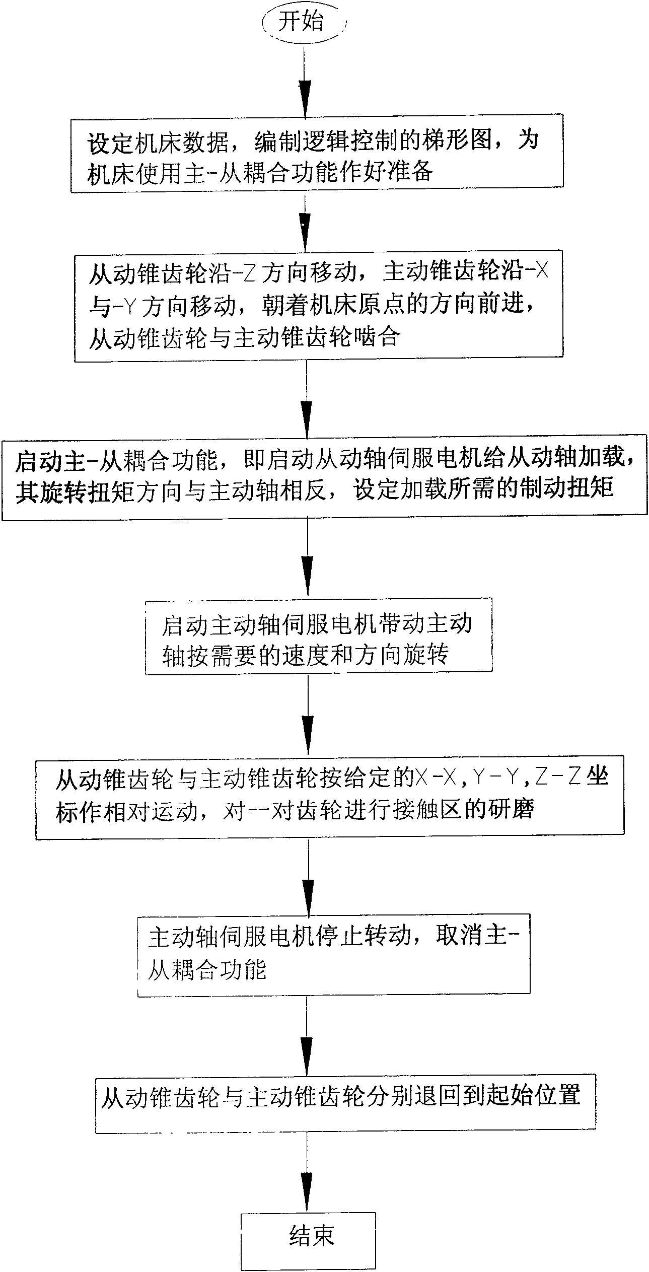
[0030] figure 2 It is a schematic plan view of the structure of the loading braking torque device of the present invention; image 3 It is a flowchart of the control method of the present invention.

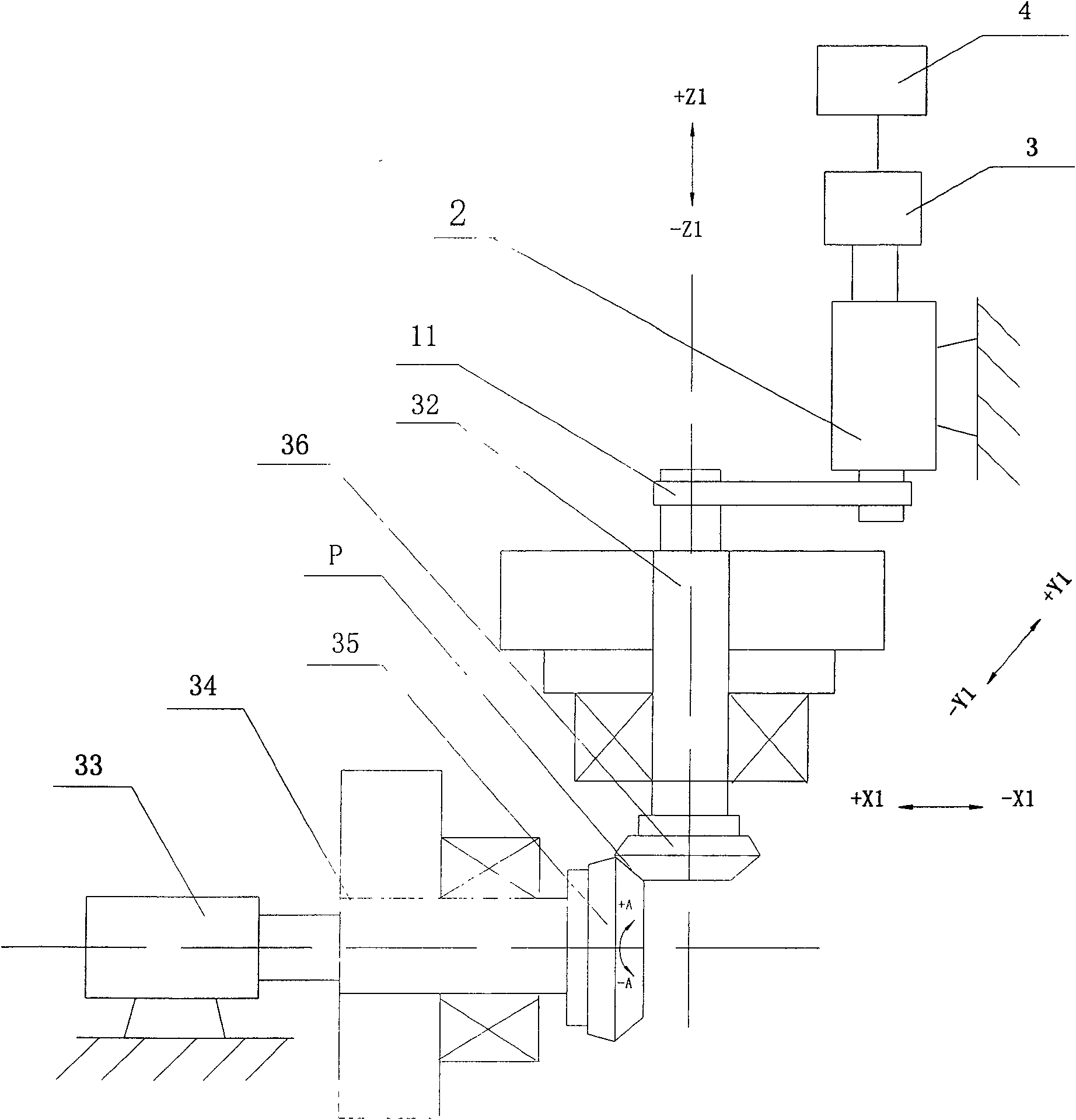
[0031] Such as figure 2 As shown, X-X, Y-Y, and Z-Z represent three linear coordinate axes respectively, and the Z-Z axis is defined as moving the driven spiral bevel gear 136 to move axially along its axis; the X-X axis is defined as the driving spiral bevel gear 135 moving along its axis Axial movement; Y-Y axis is defined as the active spiral bevel gear 135 moves along the direction perpendicular to the X-X axis and Z-Z axis, and its value is the center line of the active spiral bevel gear 135 relative to the center line of the driven spiral bevel gear 136 height difference.

[0032] The present invention provides a loading and braking torque devic...


PUM


Abstract

The invention discloses a loading braking torque device for a numerical control spiral bevel gear lapping machine and a control method thereof. The device comprises a driving shaft, a driving spiral bevel gear, a driving shaft servomotor, a driven shaft which has an angle of 90 degrees with the driving shaft, a driven spiral bevel gear, a device which pushes the driven spiral bevel gear and the driving spiral bevel gear to move along the axial direction of the device respectively, and a spindle driving unit of a numerical control system. The control method comprises the following steps: realizing a preparation stage of a driving-driven coupling function and a gear engagement stage; starting a driving-driven coupling function stage; starting a driving shaft rotating stage; beginning a lapping circulation stage; canceling the driving-driven coupling function stage; returning to an initial position stage; and finishing the lapping. The device has the advantages that the device changes the gear lapping of a mechanical structure, has steady operation, can lap at high speed, improve the speed by 1.5 times compared with the lapping speed of the prior technology, has good lapping effect, reduces noises during the engagement, and improves the service life.

Description

technical field [0001] The invention relates to a numerically controlled gear grinding machine, in particular to a device for loading a braking torque on a numerically controlled spiral bevel gear grinding machine and a control method thereof. Background technique [0002] In order to prolong the service life of spiral bevel gears in automobile parts, reduce the noise during driving, and further improve the contact area of ​​the gears, it is necessary to grind the tooth surfaces of each pair of spiral bevel gears that mesh with each other on a gear grinding machine. When the grinding machine grinds the contact area of ​​the tooth surface of the spiral bevel gear, loading grinding should be carried out. Loading the ground gear can effectively improve the meshing effect of the gear contact area. [0003] figure 1 It is a schematic plan view of a grinding structure of a gear grinding machine loaded with braking torque in the prior art. [0004] Such as figure 1 As shown, the...

Claims


Application Information

Patent Timeline
Patent Type & Authority Patents(China)
IPC IPC(8): B23F19/02B23F23/00G05B19/18
Inventor 冯玉英刘新瑞
Owner 通用技术集团天津第一机床有限公司
Why Eureka
Try Eureka