Assembly structure of spindle box of vertical machining center

A vertical machining center and assembly structure technology, applied in the direction of metal processing equipment, metal processing machinery parts, manufacturing tools, etc., can solve the problem of inability to guarantee machining accuracy, unstable force of the spindle box, unstable force of the spindle box, etc. problem, to achieve the effect of improving dimensional accuracy and smoothness, improving mobile form, and reducing noise decibel value

Active Publication Date: 2016-07-27
临清市顺佳机械设备有限公司
View PDF6 Cites 0 Cited by
  • Summary
  • Abstract
  • Description
  • Claims
  • Application Information

AI Technical Summary

Problems solved by technology

The spindle box is installed on the column to form a cantilever structure, and the spindle is installed on the free end of the spindle box, which is away from the connection end of the spindle box and the column. The weight of the spindle box and the servo drive motor of the spindle is very large, and the spindle box is free The end will bear a large force, which seriously affects the reliability of the cooperation between the column and the spindle box under the cantilever connection structure, resulting in unstable force on the spindle box during processing, unstable spindle operation, and vibration during processing. The processing accuracy cannot be guaranteed, and it also causes uneven wear on the hard rail surface, which increases the frequency of wear and replacement
The cantilever structure and the surface contact track lead to unstable force on both ends of the spindle box at different feed rates, especially during low-speed heavy cutting, the spindle vibration is very obvious, which seriously affects the machining accuracy

Method used


Image

  • Assembly structure of spindle box of vertical machining center
  • Assembly structure of spindle box of vertical machining center
  • Assembly structure of spindle box of vertical machining center

Examples


Embodiment Construction

[0021] In order to facilitate the understanding of the technical solution of the present invention, the technical content involved in it will be further described below in conjunction with the accompanying drawings.

[0022] In the description of the present invention, it should be noted that the terms "left", "right", "front", "rear", "upper", "lower", "inner", "outer", etc. indicate the orientation or positional relationship Based on the orientation or positional relationship shown in the drawings, it is only for the convenience of describing the present invention and simplifying the description, and does not indicate or imply that the referred device or element must have a specific orientation, be constructed and operated in a specific orientation, and therefore cannot be construed as a limitation of the invention.

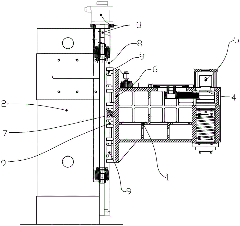
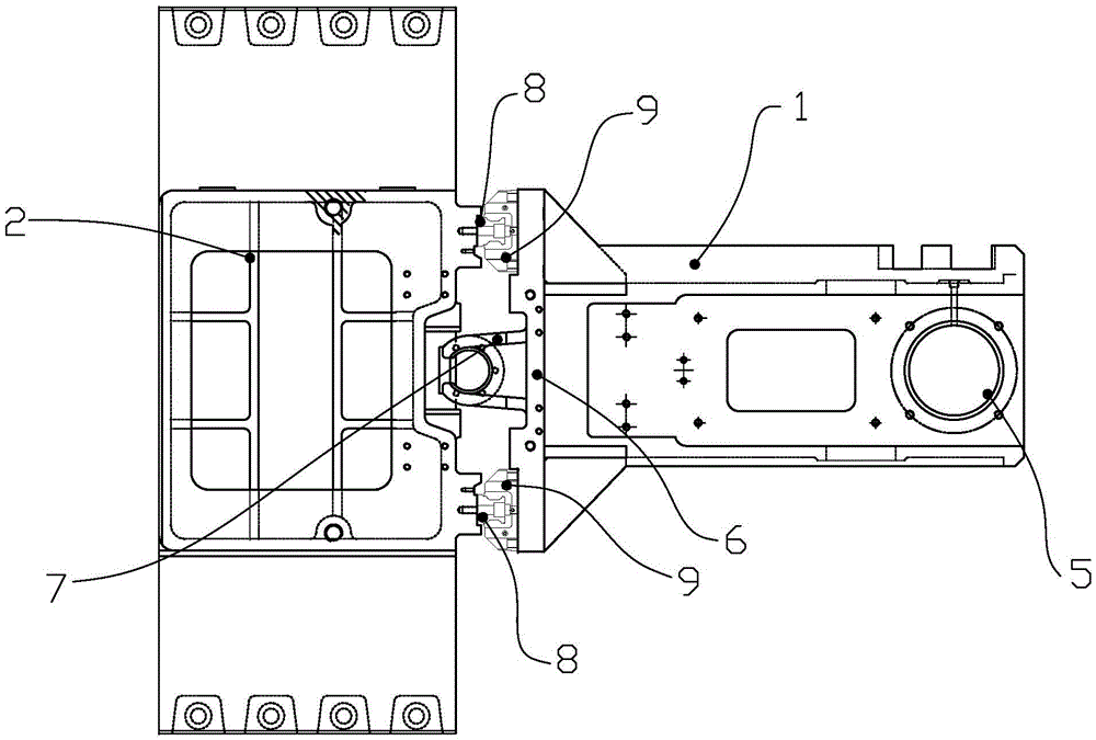
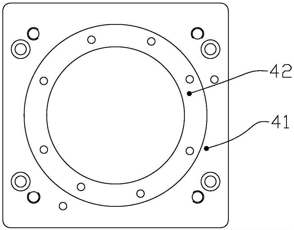
[0023] Such as Figure 1 to Figure 4 as shown,

[0024] The assembly structure of the spindle box of the vertical machining center includes a spindle box 1, ...


PUM


Abstract

The invention discloses an assembling structure for a main shaft box of a vertical type processing center. The assembling structure comprises the main shaft box and a main shaft connection plate with a split type structure, wherein the main shaft connection plate consists of a main shaft box connection plate and a main shaft servo motor connection plate; a circular through hole is formed in the center of the main shaft box connection plate; the apertures of the upper end position and the lower end position of the circular through hole are greater than the aperture of the middle position of the circular through hole; the main shaft servo motor connection plate is a cylinder; a circular through hole coaxial with the main shaft servo motor connection plate is formed in the center of the main shaft servo motor connection plate; the outer circumferential surface is of a one-stage steplike shape, and the upper outer diameter is smaller than the lower outer diameter; the circular circumferential surface of the middle of the circular through hole in the main shaft box connection plate is in interference fit with the outer circumferential surface of the lower end of the main shaft servo motor connection plate. According to the assembling structure, the assembling precision between the main shaft connection plate and the main shaft box as well as between the main shaft connection plate and a main shaft can be respectively adjusted, and the coaxiality error of the main shaft and a main shaft servo motor which are assembled is obviously reduced; the rotating speed of the main shaft is increased to 20,000 r / m; obvious influence on the service life of the main shaft servo motor can be avoided; the noise decibel value of the main shaft is obviously reduced; the vibration of the main shaft box is obviously alleviated.

Description

technical field [0001] The invention belongs to the technical field of machine tool processing machinery, and in particular relates to an assembly structure of a spindle box of a vertical machining center. Background technique [0002] The spindle box is an important part of the machining center. One end of the spindle box is matched with the column so that the spindle box can slide relative to the column. The other end is a free end, and the spindle and the spindle servo motor are installed on this end. [0003] At present, the spindle box is formed by casting, and the upper end surface of the spindle box is reserved with a slot for installing the spindle servo motor. The current method adopted is to fixedly install an integrally formed spindle mounting plate in the slot to realize the cooperative connection between the spindle box and the spindle servo motor. This kind of matching method requires high processing accuracy of the spindle box and the spindle mounting plate, ...

Claims


Application Information

Patent Timeline
Patent Type & Authority Patents(China)
IPC IPC(8): B23B19/00B23Q1/01
CPCB23Q1/01B23Q1/70
Inventor 梁红军
Owner 临清市顺佳机械设备有限公司
Why Eureka
Try Eureka