Centrifugal fan with vortex preventing sheets

A centrifugal fan and vortex technology, which is used in electromechanical devices, mechanical equipment, and mechanical energy control. Low decibel value and compact structure

Pending Publication Date: 2022-04-15
FANS TECH ELECTRIC CO LTD
View PDF2 Cites 0 Cited by
  • Summary
  • Abstract
  • Description
  • Claims
  • Application Information

AI Technical Summary

Problems solved by technology

The setting of the deflector can play the role of reducing eddy current and reducing noise at the corner of the air outlet, but it is still difficult to solve the problem of significantly increased backflow at the volute tongue of the fan when the size of the fan is designed to be compact
[0005] Therefore, the centrifugal fan in the prior art has the problems of high noise decibel value, unstable air outlet and uncompact structure.

Method used


Image

  • Centrifugal fan with vortex preventing sheets
  • Centrifugal fan with vortex preventing sheets
  • Centrifugal fan with vortex preventing sheets

Examples


Embodiment 1

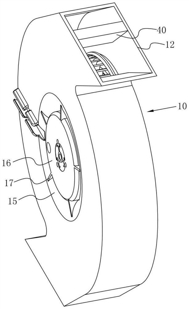
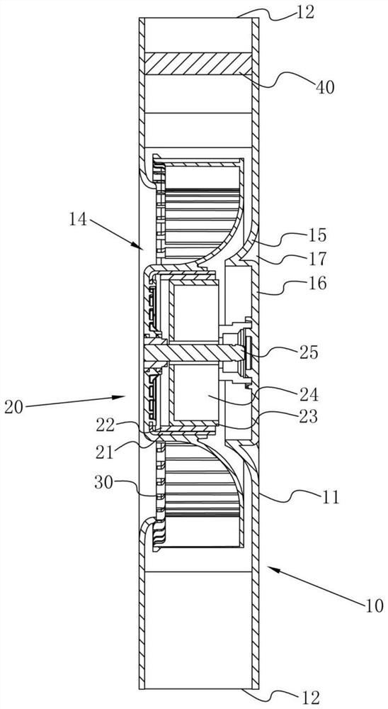
[0036] refer to Figure 1-3 , a centrifugal fan with anti-vortex plate, including a volute 10, a driving device 20 and an impeller 30. The main body 11 is provided with an air inlet 14, the driving device 20 drives the impeller 30 to rotate in the volute 10, and the rotating impeller 30 drives the air to enter the interior of the main body 11 from the air inlet 14, and is discharged through the air outlet 12 to realize the air supply of the centrifugal fan. Function.

[0037] The driving device 20 is respectively connected with the volute 10 and the impeller 30. The volute 10 includes a main body 11, an air outlet 12 and a volute tongue 13. The air outlet 12 and the volute tongue 13 are fixedly connected with the main body 11, and the impeller 30 is located in the volute 10. The volute 10 is fixedly connected with an anti-vortex sheet 40, the anti-vortex sheet 40 extends toward the air outlet 12, and the distance between the anti-vortex sheet 40 and the rotation center of the...

Embodiment 2

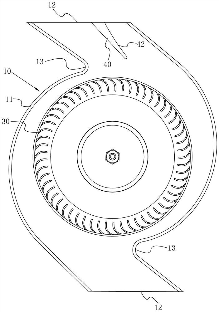
[0066] refer to Figure 5 , a centrifugal fan with an anti-vortex sheet, the difference from Embodiment 1 is that there are two anti-vortex sheets 40 in total, and the two anti-vortex sheets 40 correspond to the two volute tongues 13 one-to-one respectively.

[0067] This embodiment has the following advantages:

[0068] When the conventional fan is designed with dual air outlets, the parameters of the volutes 10 at the two air outlets 12 affect each other, resulting in insufficient air diffusion in each section of the volutes 10, and it is difficult to optimize the parameters of the volutes 10. By arranging the anti-vortex sheet 40 in the volute 10, after the flow is divided by the anti-vortex sheet 40, the problem of insufficient airflow diffusion in the volute 10 is effectively improved, and the air flow in the volute 10 is further controlled by the anti-vortex sheet 40, so that The outlet flow field structure of the centrifugal fan designed with double air outlets 12 has ...

Embodiment 3

[0070] refer to Image 6 , a centrifugal fan with an anti-vortex sheet, which is different from Embodiment 1 in that: the anti-vortex sheet 40 is provided with a plurality of shunt holes 41 .

[0071] This embodiment has the following advantages:

[0072] By arranging the diverting holes 41 on the anti-vortex sheet 40, the air on both sides of the anti-vortex sheet 40 can flow through the diverting holes 41, so that the anti-vortex sheet 40 can not only play a certain diverting function, but also take into account the output of the centrifugal fan. The performance of the air volume is improved, and it has the effect of controlling the noise. It achieves the advantages of good noise reduction effect, good air output stability and large output air volume.


PUM


Abstract

The centrifugal fan comprises a volute, a driving device and an impeller, the driving device is connected with the volute and the impeller, the volute comprises a body, an air outlet and a volute tongue, the air outlet and the volute tongue are both fixedly connected with the body, the impeller is located in the volute, the volute is fixedly connected with the anti-vortex piece, and the anti-vortex piece extends towards the air outlet. The distance D2 between the anti-vortex sheets and the rotation center of the impeller is equal to a1 * D1, the coefficient a1 is 1.05-1.4, and D1 is the maximum outer diameter of the impeller. The centrifugal fan has the beneficial effects that air is shunted in advance through the vortex preventing pieces, so that backflow at the volute tongue is effectively reduced, the vortex structure at the air outlet is obviously improved, vibration and noise generated by unstable airflow at the volute tongue can be weakened, the effect of increasing the exhaust air volume of the centrifugal fan is achieved, and the service life of the centrifugal fan is prolonged. The fan has the advantages of being low in noise decibel value, stable in air outlet and compact in structure.

Description

technical field [0001] The invention relates to the technical field of centrifugal fans, in particular to a centrifugal fan with an anti-vortex sheet. Background technique [0002] Centrifugal fans are widely used in refrigeration and air conditioners, household purifiers and other equipment, and can play the role of air supply, dust removal, heat dissipation and cooling. The use environment of centrifugal fans includes but is not limited to the above facilities and equipment. The centrifugal fan includes a volute assembly, a motor assembly and an impeller assembly, and the motor assembly drives the impeller assembly to rotate in the volute assembly, thereby realizing the function of air supply. In order to make the structure of the centrifugal fan more compact, the thickness of the centrifugal fan needs to be reduced. As a result, the ratio of the thickness to the diameter of the centrifugal fan is not within the recommended range for the design of the centrifugal fan. The...

Claims


Application Information

Patent Timeline
Patent Type & Authority Applications(China)
IPC IPC(8): F04D29/42F04D29/66F04D17/16F04D25/08H02K7/14
Inventor 袁小永莫远忠
Owner FANS TECH ELECTRIC CO LTD
Why Eureka
Try Eureka