Pipeline robot

A pipeline robot and controller technology, which is applied in the direction of special pipes, pipe components, mechanical equipment, etc., can solve the problems of poor driving performance and poor waterproof performance

Active Publication Date: 2018-09-07
南京管科智能科技有限公司
View PDF6 Cites 11 Cited by
  • Summary
  • Abstract
  • Description
  • Claims
  • Application Information

AI Technical Summary

Problems solved by technology

[0003] The purpose of the present invention is to provide a pipeline robot to solve the techni...

Method used


Image

  • Pipeline robot
  • Pipeline robot
  • Pipeline robot

Examples


Embodiment 1

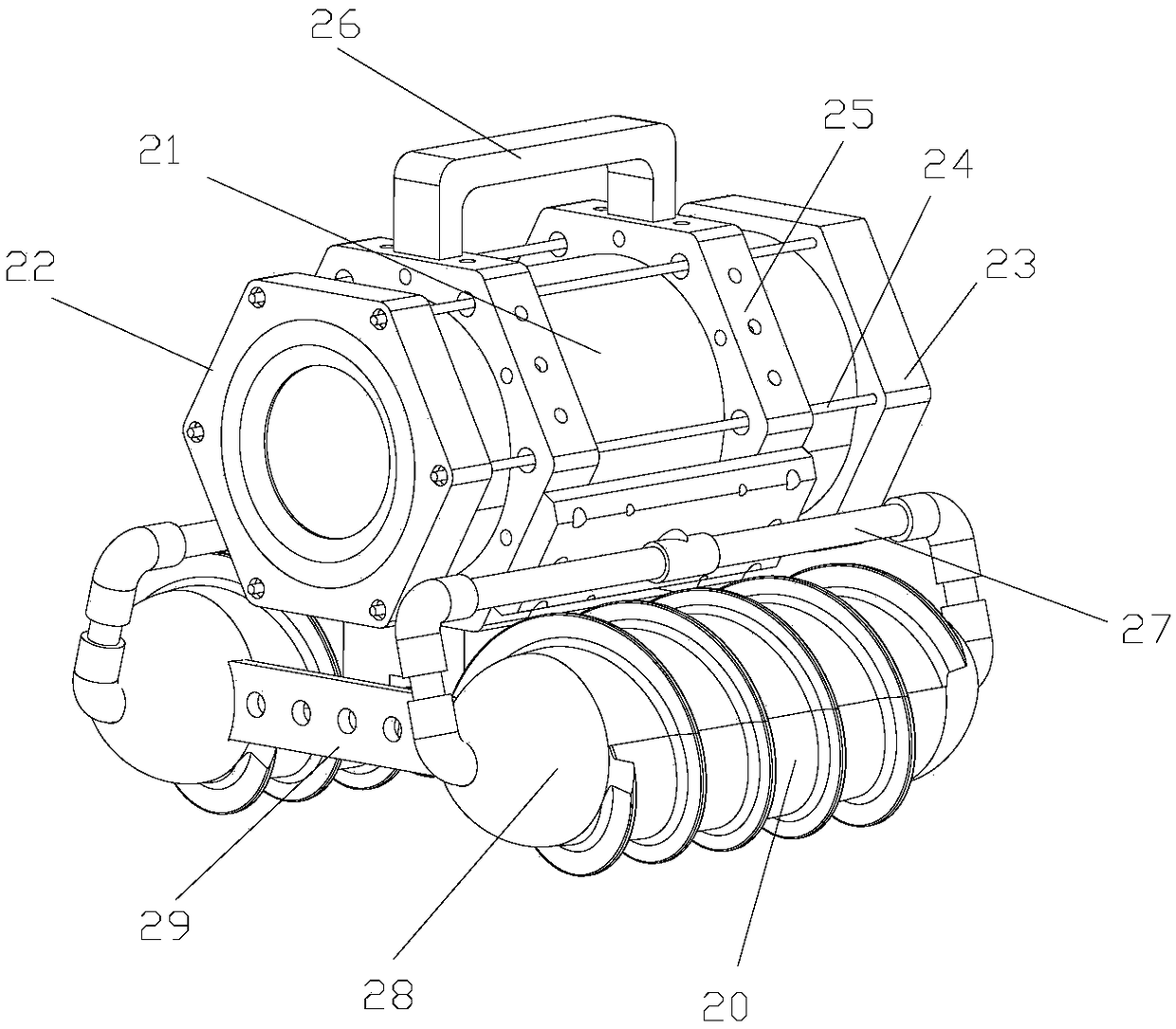
[0057] Such as Figure 1-18 As shown, a pipeline robot includes a bracket and two driving rollers that are rotatably arranged on the bracket, and a controller fixed on the bracket. The controller is arranged in the first cylinder 21, and the first cylinder is fixed on the bracket. above; the two ends of the first cylinder 21 are provided with internal threads, the front end cover 22 and the rear end cover 23 are provided with external threads, the first cylinder is threadedly connected with the front end cover and the rear end cover, and the threaded connection is convenient for disassembly installed and connected securely. The front end cover includes a front cavity and a transparent cover plate, a camera is arranged in the front cavity, the transparent cover plate is sealed and arranged at the front end of the cavity, and the camera is electrically connected to the controller.

[0058] In other embodiments, the first cylinder may be a structure with one end integrally close...

Embodiment 2

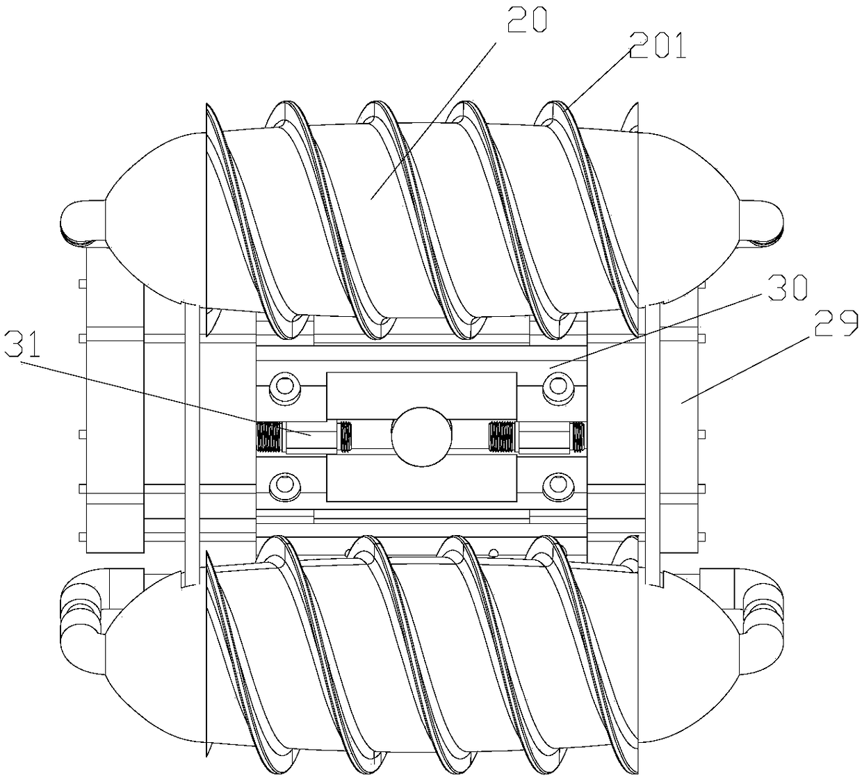
[0088]In this example, if Figure 19 As shown, the outer peripheral surface of the housing 20 is uneven, with spiral grooves and spiral protrusions, and the intersection line between the plane passing through the axis of the housing and the outer peripheral surface of the housing is a sinusoidal curve; the spiral blade 201 is located on the protrusions.

[0089] Because there will be some silt in the pipeline, when the pipeline robot walks in the pipeline, the lower part of the shell will sink into the silt, and the outer peripheral surface of the shell will be in full contact with the silt. By designing the surface of the shell to be uneven, the distance between the shell and the The contact surface of the inner ratio of the pipe increases the friction, prevents slipping and improves the driving performance.

[0090] In this embodiment, the profile of the end face of the spiral blade is a horizontal line at the top and symmetrical arcs on both sides;

[0091] In the plane wh...


PUM

PropertyMeasurementUnit
Widthaaaaaaaaaa

Abstract

The invention discloses a pipeline robot. The pipeline robot comprises a support, at least two driving rollers and a controller fixedly arranged on the support; each driving roller comprises a drivingbody and a shell which wraps around the driving body; the shells are of cylindrical shapes, and spiral blades are fixedly arranged on the outer peripheral surfaces of the shells along the length direction of the shells; each driving body comprises an outer cylinder and an inner cylinder arranged inside the outer cylinder, motors are fixedly arranged inside the inner cylinders, the output shafts of the motors are sleeved with first rotating pieces, and the outer peripheral surfaces of the first rotating pieces are fixedly connected with the inner walls of the outer cylinders in a sealing mode;the other ends of the inner cylinders are provided with second connecting pieces, and the inner cylinders and the outer cylinders are rotationally connected together through the second connecting pieces, and the second connecting pieces are hermetically connected with the inner cylinders and the outer cylinders correspondingly; and the shells sleeve the outer cylinders, and the motor is electrically connected with the controller. The pipeline robot has the beneficial effects that the motor is fixedly arranged inside the inner cylinders in a sealing mode, so that the waterproof performance isgood; the inner cylinders and the outer cylinders are enabled to be connected rotationally through the first connecting piece and the second connecting piece; and the cost is greatly reduced through the shells with the spiral blades which sleeves the outer cylinders.

Description

technical field [0001] The invention relates to a pipeline robot. Background technique [0002] The environment of municipal pipelines is very harsh, and after long-term use, it is prone to corrosion, fatigue damage, or potential internal defects of the pipeline to develop into damage and cause leakage accidents, etc., especially for water pipelines, which are also prone to blockage and other accidents. Therefore, the in-pipe detection and desilting of pipelines is a very important practical project. At present, most of the in-pipe detection and decontamination are performed manually, which is limited by factors such as the size of the pipeline and the harsh environment, resulting in high work intensity and low work efficiency. The problem currently arises with pipeline bots. However, most of the existing pipeline robots are driven by rollers, which have poor driving performance and are easy to slip. When the robot is suspended in water, the driving fails and the waterproof...

Claims


Application Information

Patent Timeline
IPC IPC(8): F16L55/32F16L101/12F16L101/30
CPCF16L55/32F16L2101/12F16L2101/30
Inventor 娄保东
Owner 南京管科智能科技有限公司
Why Eureka
Try Eureka