Middle-layer water receiving disc and mobile air conditioner with water receiving disc

A water-receiving pan and middle-layer technology, which is used in household appliances, prevention of condensation, space heating and ventilation details, etc., can solve problems such as insufficient drainage capacity of partitions, improve water removal efficiency, relieve water pressure, and expand Application-wide effects

Pending Publication Date: 2018-09-07
AUX AIR CONDITIONING LTD BY SHARE LTD
View PDF5 Cites 1 Cited by
  • Summary
  • Abstract
  • Description
  • Claims
  • Application Information

AI Technical Summary

Problems solved by technology

[0004] In view of this, the present invention aims to propose a middle water receiving tray to solve the problem of insufficient drainage capacity of partitions in mobile air conditioners

Method used


Image

  • Middle-layer water receiving disc and mobile air conditioner with water receiving disc
  • Middle-layer water receiving disc and mobile air conditioner with water receiving disc
  • Middle-layer water receiving disc and mobile air conditioner with water receiving disc

Examples


Embodiment 1

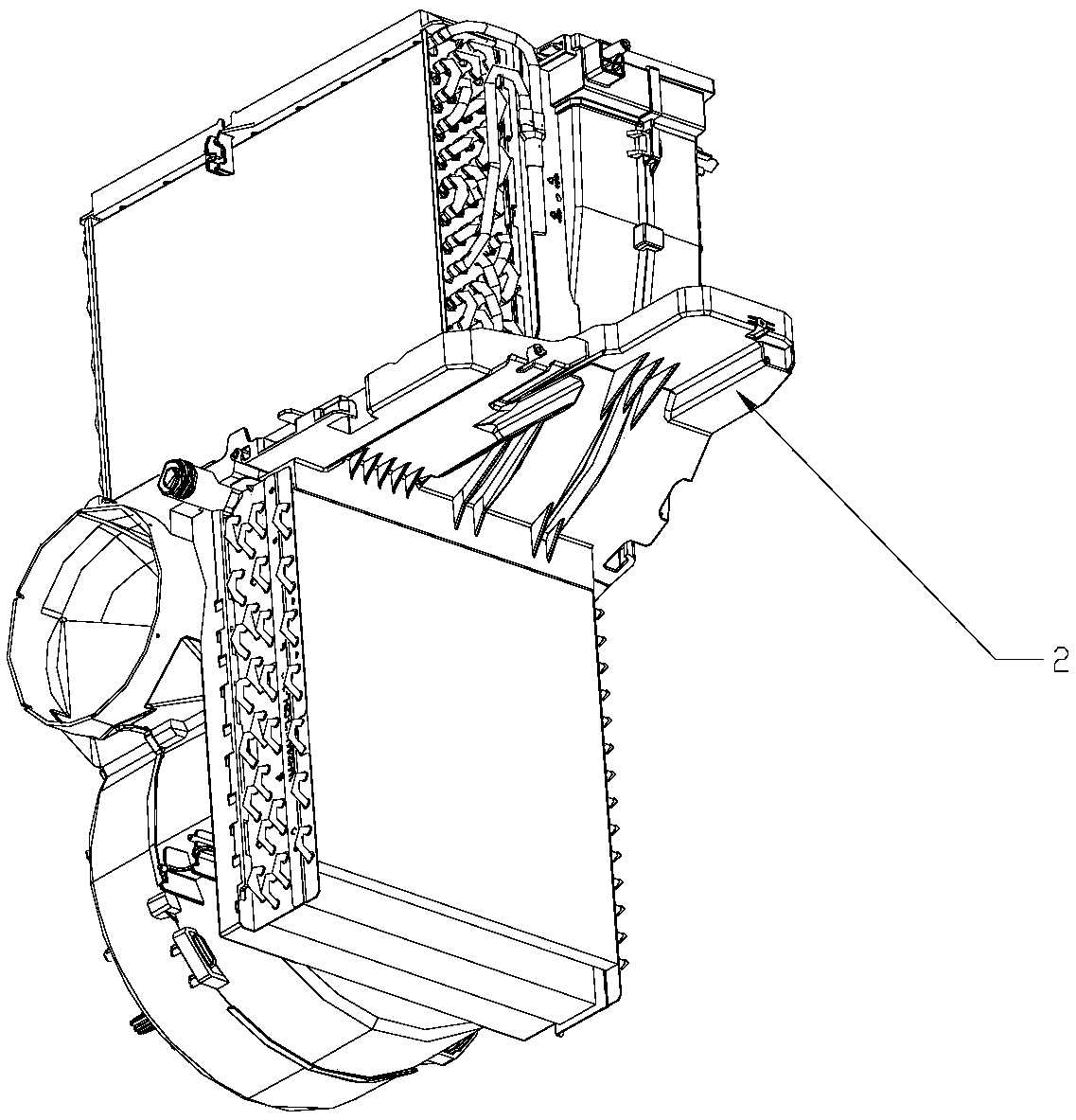
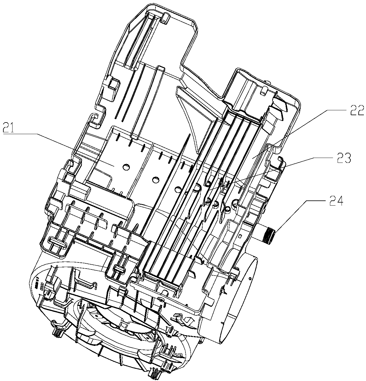
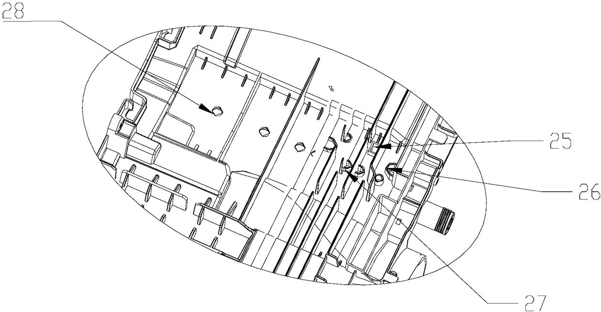
[0054] Among the present invention, the drain hole is arranged on the evaporator area 21, such as image 3 As shown, a cofferdam is provided on the drain hole, and the drain hole is divided into a first class drain hole 25, a second class drain hole 26 and a third class drain hole 27 according to the different heights of the cofferdam.

[0055] Such as Figure 4 As shown, the first type of drainage hole 25 is set as a square hole, and the first type of drainage hole 25 also includes a first cofferdam 251 and a first guide slope 252, and extends upward to a certain height along the square hole to form the first cofferdam 251. The height of the first cofferdam 251 is preferably set to 5mm-7mm, more preferably set to 7mm; the first guide slope 252 is inclined downward along the side of the square hole, and the first guide slope 252 is connected to the middle partition 2 and the first The integrated arrangement of the cofferdam 251 not only simplifies the manufacturing process, b...

Embodiment 2

[0062] The difference between the present embodiment and the first embodiment is that the first type of drain hole 25 is arranged close to other parts on the middle partition 2, that is, the cross-sectional shape of the top of the first cofferdam 251 is set as U-shaped, which is due to the In the first embodiment, the cross section of the first cofferdam 251 is in the shape of a "mouth". When the side walls of other components act as one side of the first cofferdam 251, the U-shaped cross section of the first cofferdam 251 and the side walls of other components together form a Closed "mouth" shape. In this embodiment, it is preferable to set a type of drain hole 25 on one side of the supporting rib 23, so that the supporting rib 23 can serve as one side of the first cofferdam 251. Such setting can not only save materials and reduce production costs, but also can This avoids the problem that the slit space is easily blocked due to arranging a type of downhole 25 between two row...

Embodiment 3

[0065] The difference between this embodiment and Embodiment 1 is that, as Figure 6 As shown, the fourth cofferdam 263 is formed by extending obliquely upwards around the first orifice 261, wherein the inclination angle is 3°-5° to the outside, so that the fourth cofferdam 263 forms an arc-shaped space with a wide top and a narrow bottom. Similarly, a fifth cofferdam is formed around the second orifice obliquely upward and outward by 3°-5°, so that the fifth cofferdam forms an arc-shaped space with a wide top and a narrow bottom.

[0066] The cofferdams on the second-type downholes 26 and the third downholes 27 are set in a shape that expands from bottom to top to the outside, which is beneficial for condensed water to enter the downholes. In addition, the expanded cofferdams can increase the capacity of the arc-shaped space. And the setting of the cofferdam with a wide top and a narrow bottom is conducive to increasing the water flow pressure, and can promote the rapid passa...


PUM


Abstract

The invention provides a middle-layer water receiving disc and a mobile air conditioner with the water receiving disc. The middle-layer water receiving disc comprises a middle partition plate, the middle partition plate is obliquely arranged and provided with supporting ribs, water falling holes and a water drainage nozzle, the supporting ribs are provided with at least one flow guiding hole, theflow guiding holes are used for guiding condensate water to the water drainage nozzle, the water drainage nozzle is used for draining condensate water guided from the flow guiding holes, and the waterfalling holes are provided with cofferdams. According to the middle-layer water receiving disc, the middle partition plate is provided with the water falling holes and the water drainage nozzle simultaneously, the water falling holes have multiple modes, therefore, the water drainage function of the middle-layer water receiving disc is greatly improved, the probability that the condensate water is accumulated on the middle-layer water receiving disc is reduced, and the mobile air conditioner with the middle-layer water receiving disc has the good working performance.

Description

technical field [0001] The invention relates to the technical field of air conditioners, in particular to a middle-layer water receiving tray and a mobile air conditioner with the water receiving tray. Background technique [0002] During normal operation of the mobile air conditioner, condensed water is usually produced on the surface of the evaporator and the outer wall of the air outlet. Unreasonable discharge or recovery of condensed water will not only lead to waste of cooling capacity, but also affect the environment of the mobile air conditioner. [0003] Usually, a middle partition is set in the mobile air conditioner to layer it up and down. The upper layer is equipped with evaporator and air supply volute parts, and the lower layer is equipped with condenser parts. At the same time, the condensed water generated in the upper layer enters the lower area through the middle partition for secondary secondary use or discharge. The middle partition in the prior art usua...

Claims


Application Information

Patent Timeline
Patent Type & Authority Applications(China)
IPC IPC(8): F24F13/22
CPCF24F13/222
Inventor 叶鲁伟冷晓刚成日雄陈明侠王长刚耿德国
Owner AUX AIR CONDITIONING LTD BY SHARE LTD
Why Eureka
Try Eureka