
Model adjustment method based on 3D imaging technology and model generation device

An adjustment method and model generation technology, applied in image communication, electrical components, stereo systems, etc., can solve the problem of single function of 3D image shooting terminal, and achieve the effect of multiple display functions

Active Publication Date: 2018-09-07
UNRE SHANGHAI INFORMATION TECH CO LTD
View PDF6 Cites 4 Cited by
  • Summary
  • Abstract
  • Description
  • Claims
  • Application Information

AI Technical Summary

Problems solved by technology

[0006] The technical problem to be solved by the present invention is to overcome the defect that the 3D image shooting terminal in the prior art has a single function and cannot provide users with more user experience, and provide a method that can adjust the size and details of the 3D model so that the 3D model can be displayed More states, a model adjustment method and a model generation device based on 3D imaging technology that provide more display functions

Method used


Image

  • Model adjustment method based on 3D imaging technology and model generation device
  • Model adjustment method based on 3D imaging technology and model generation device

Examples


Embodiment 1

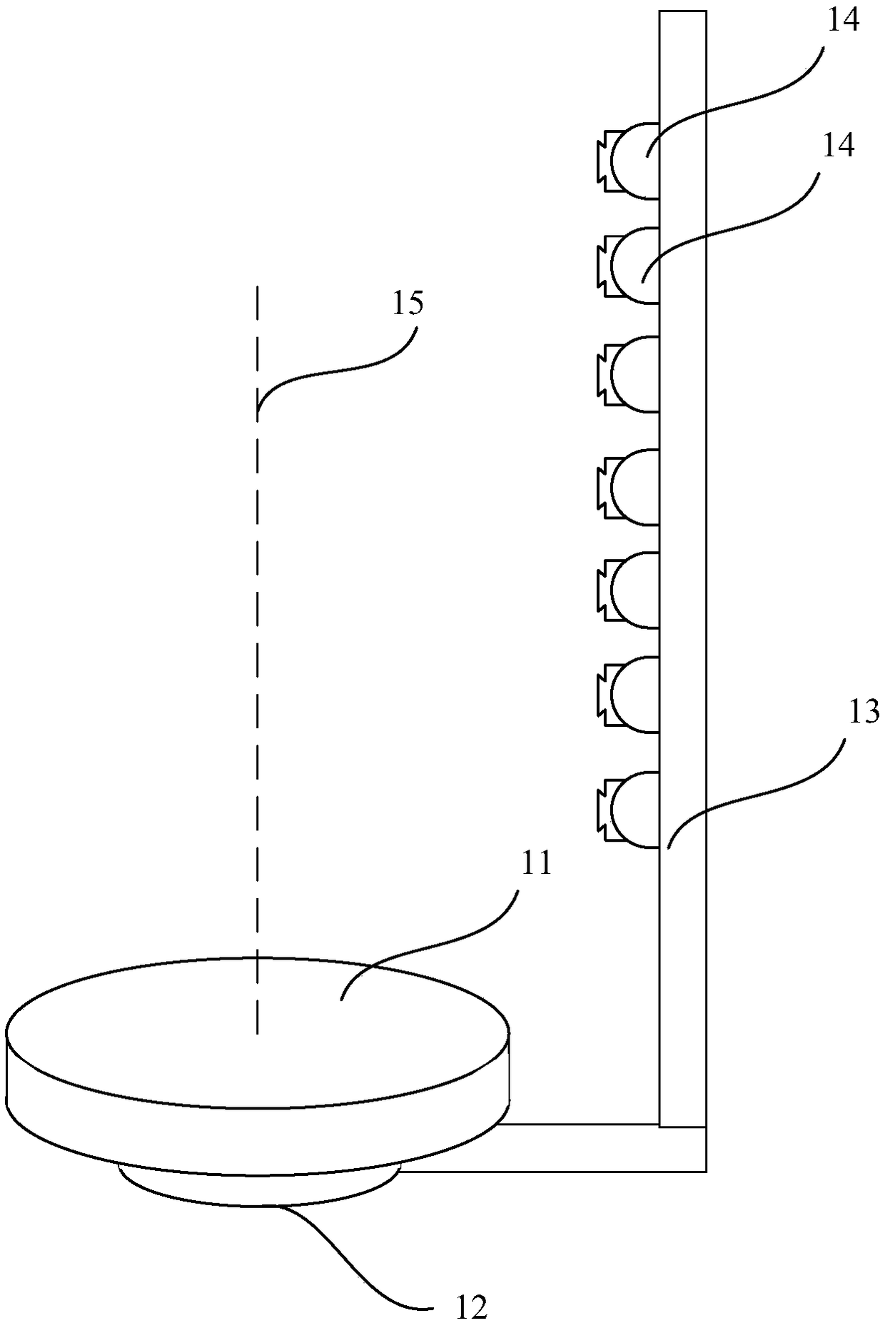
[0041] see figure 1 , the present embodiment provides a model generation device, the model generation device includes a tray 11, a support part 12, a rotating device, a support rod 13, seven 3D cameras 14 and a processing end.

[0042] In this embodiment, the processing end is a computer, and the processing end may also be a cloud server, and the cloud server is used to perform data calculation by transmitting data to the cloud server.

[0043] The tray is installed on the support part through the rotation device, and the tray rotates horizontally on the support part around the axis of the rotation device through the rotation device.

[0044] The support rod is perpendicular to the plane where the pallet is located.

[0045] The seven 3D cameras are vertically arranged side by side on the support rod.

[0046] The shooting direction of the 3D camera is from the 3D camera to a point on the axis 15 .

[0047] The 3D camera is used to rotate the tray once to capture all 3D ima...

Embodiment 2

[0072] This embodiment is basically the same as Embodiment 1, the only difference is:

[0073] The processing end is used to move the target model point to the specified direction by the target distance according to the direction data, and then move the model points around the target model point to the specified direction to adjust the distance, each surrounding model point The adjustment distance is passed by Y=-(a X )+b+1, where Y is the adjustment distance greater than 0, X is the distance from the surrounding model points to the target model point, a is a coefficient greater than 1 and less than 2, and b is the target distance.

[0074] Correspondingly, step 105 in Embodiment 1 is replaced by moving the target model point by the target distance in the specified direction according to the direction data, and then moving the model points around the target model point in the specified direction for an adjustment distance, each The adjustment distance of a surrounding model p...


PUM


Abstract

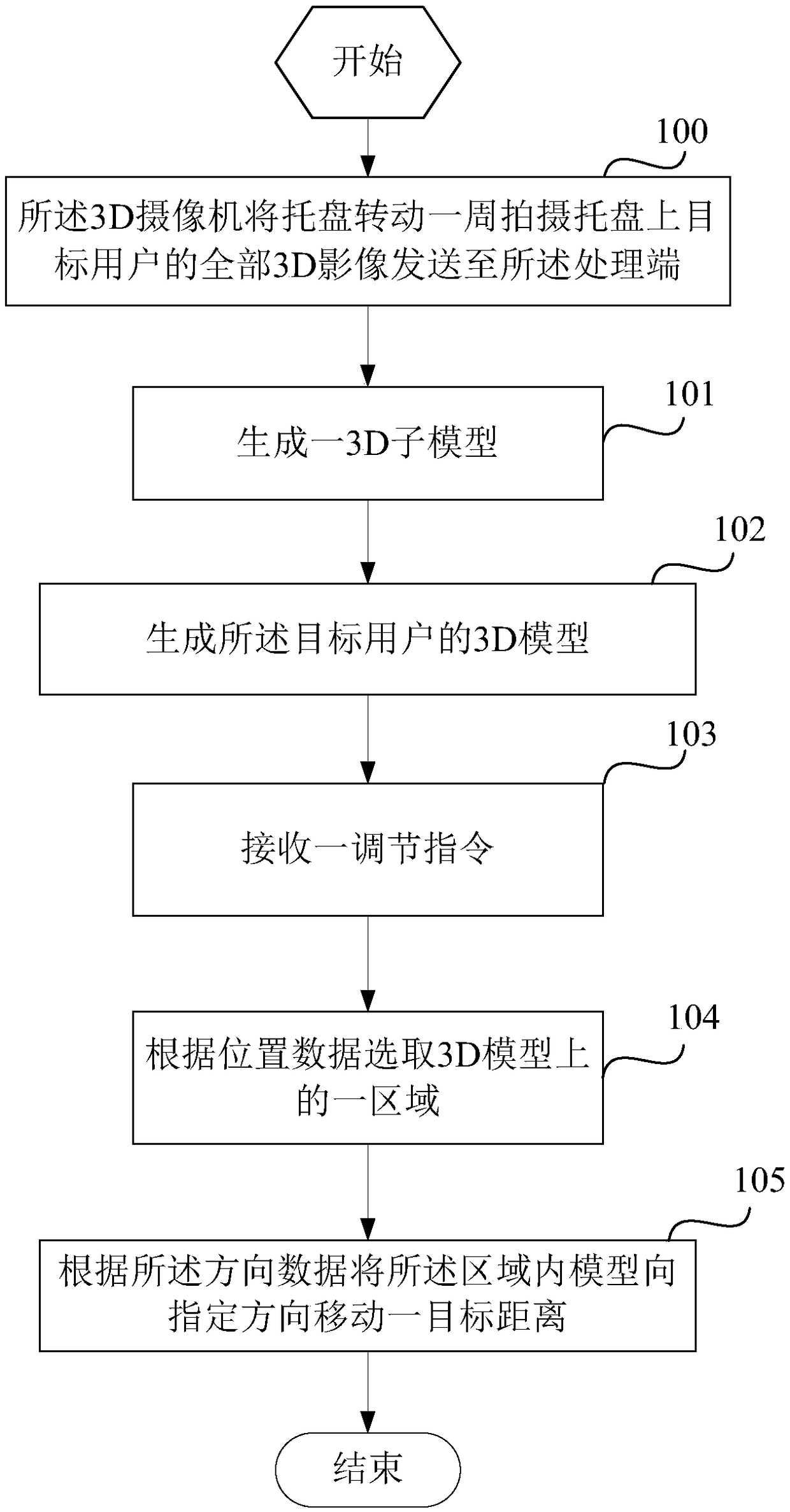
The invention discloses a model adjustment method based on a 3D imaging technology and a model generation device. The model adjustment method includes the following steps: acquiring a 3D model of a target user; receiving an adjustment instruction, wherein the adjustment instruction includes position data, direction data and degree data; selecting an area on the 3D model according to the position data; and moving the model in the area to a specified direction for a target distance according to the direction data, wherein the target distance is a distance recorded in the degree data. According to the model adjustment method and the model generation device disclosed by the invention, the 3D model of the whole body of the user can be conveniently and quickly acquired, the size and details of the 3D model can also be adjusted to ensure that the 3D model can display more states, and thus the model generation device and the 3D model generated by the model generation device can achieve more display functions.

Description

technical field [0001] The invention relates to a model adjustment method and a model generation device based on 3D imaging technology. Background technique [0002] A 3D camera is a camera made with a 3D lens. It usually has more than two camera lenses with a distance close to that of the human eye, and can capture different images of the same scene similar to what the human eye sees. Holographic 3D has more than 5 lenses on the disk, and the same image can be viewed in all directions through dot grating imaging or rhombus grating holographic imaging, as if you are on the scene. [0003] The first 3D camera So far the 3D revolution has all revolved around Hollywood blockbusters and major sports events. With the advent of 3D cameras, this technology is one step closer to home users. After the launch of this camera, we will be able to use 3D lenses to capture every memorable moment in life, such as a child's first step, college graduation celebration and so on. [0004] 3D...

Claims


Application Information

Patent Timeline
IPC IPC(8): H04N13/243H04N13/275
Inventor 孙燕生
Owner UNRE SHANGHAI INFORMATION TECH CO LTD
Learn More