Steel rail fat edge milling device

A milling device and rail technology, applied in milling machine equipment, details of milling machine equipment, metal processing, etc., can solve the problems such as the inability to adjust the milling position, the extremely high requirements for clamping guide rail components, and the large vibration of single-layer milling, so as to achieve the milling effect. Better, better clamping, better milling results

Pending Publication Date: 2018-09-11
CHANGZHOU HUAMING AUTOMATION TECH CO LTD +1
View PDF0 Cites 1 Cited by
  • Summary
  • Abstract
  • Description
  • Claims
  • Application Information

AI Technical Summary

Problems solved by technology

The existing milling devices are all single-layer milling and the milling position cannot be adjusted, so the applicability is poor. The single-layer milling has high requirements for the milling cutter for the milling work, so the cost is high, and the vibration of the single-layer milling is also large. The components of the guide rail are extremely demanding, the milling speed is slow, and the milling accuracy is not good

Method used


Image

  • Steel rail fat edge milling device
  • Steel rail fat edge milling device
  • Steel rail fat edge milling device

Examples


Embodiment 1

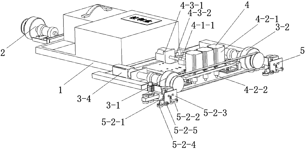
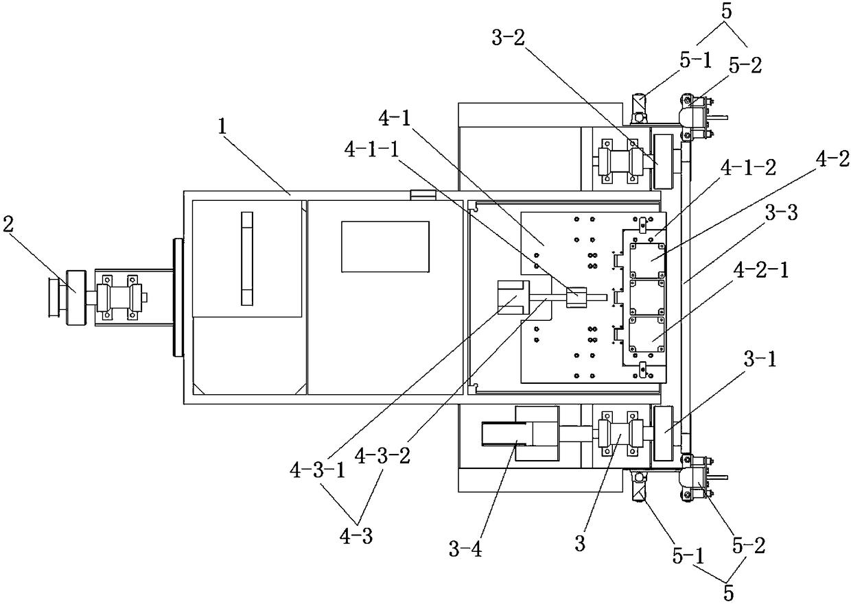
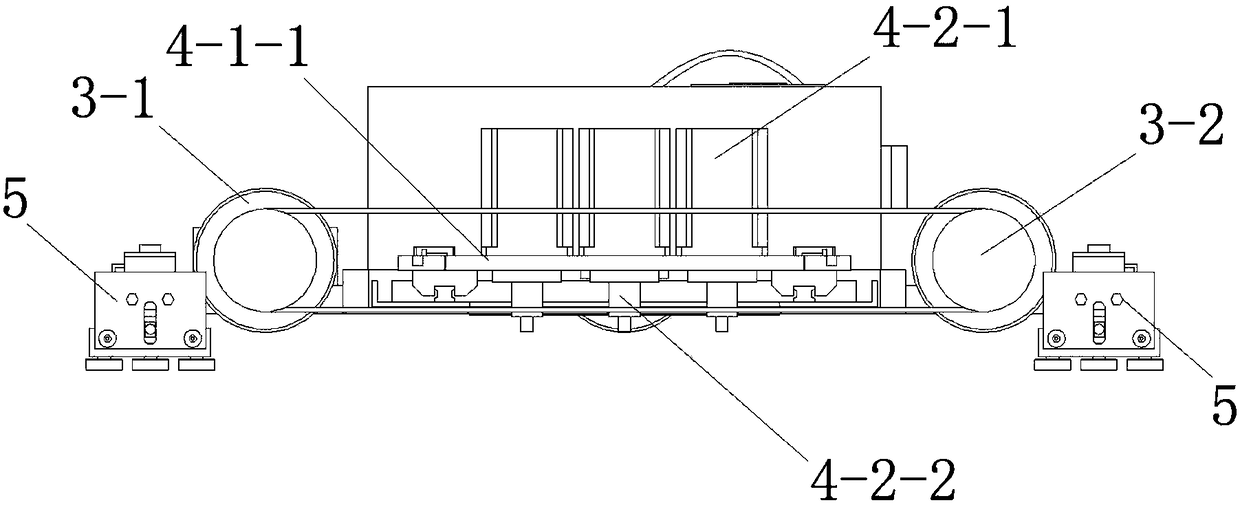
[0037] See Figure 1 to Figure 9 , The rail fat edge milling device of the present embodiment includes a vehicle frame 1, a working part and a support wheel 2.

[0038] The working part and the supporting wheels 2 are installed on both sides of the vehicle frame respectively. The working part includes a traveling mechanism 3 , a milling mechanism 4 and a multiple guide wheel clamping mechanism 5 . The running mechanism 3 and the support wheel 2 ride on two steel rails respectively. The driving frame 1 moves along the rail. The milling mechanism 4 includes a bottom plate 4-1, a milling cutter assembly 4-2 and an adjustment assembly 4-3. The multi-guide wheel clamping mechanism 5 clamps a steel rail, and moves along the steel rail following the vehicle frame 1. Base plate 4-1 is slidably connected on vehicle frame 1. The milling cutter assembly 4-2 is installed on the side edge of the steel rail that the base plate 4-1 faces toward the multi-guidance wheel clamping mechanis...

Embodiment 2

[0047] This embodiment is basically the same as Embodiment 1, the difference is:

[0048] The milling cutter assembly 4-2 of working part is provided with multiple along the moving direction of vehicle frame 1 on the motor mounting plate 4-1-2 of base plate 4-1. The installation positions of multiple milling cutter assemblies 4-2 are gradually approaching or away from the edge of the motor mounting plate 4-1-2 according to one end of the motor mounting plate 4-1-2 toward the other end.

Embodiment 3

[0050] This embodiment is basically the same as Embodiment 1, the difference is:

[0051] The rail fat edge milling device of this embodiment includes a vehicle frame 1 and a working part.

[0052] The supporting wheel 2 is replaced by another working part.

[0053] During use, the vehicle frame 1 is placed on the track, so that the driving wheel 3-1 and the driven wheel 3-2 of a traveling mechanism 3 ride on a steel rail of the track, and the driving wheel 3-1 and the driven wheel 3-2 of the other traveling mechanism 3 and the The moving wheel 3-2 rides on another rail of the track, adjusts the multi-guide wheel clamping mechanism 5, and squeezes the hinged plate 5-2-3 by rotating the screw on the hinged rod 5-2-2 to make the roller mounting plate 5 -The rollers on the 2-4 and the rollers on the fixed wheel frame 5-1 clamp the rail, the driving drive motor 3-4 drives the driving wheel 3-1 to rotate, and the driving wheel 3-1 drives the driven wheel 3 through the synchronous ...


PUM


Abstract

The invention discloses a steel rail fat edge milling device which comprises a frame, a working part and a supporting wheel, wherein the working part and the supporting wheel are separately mounted ontwo sides of the frame; the working part comprises a walking mechanism, a milling mechanism and a multi-guide wheel clamping mechanism; the walking mechanism and the supporting wheel are separately overlaid on two steel rails; the driving frame moves along the steel rails; the milling mechanism comprises a bottom plate, a milling cutter assembly and an adjusting assembly; the multi-guide wheel clamping mechanism clamps one steel rail and moves along the steel rails along with the frame; the bottom plate is slidably connected to the frame; the milling cutter assembly is mounted at the edge ofone side, facing the steel rails clamped by the multi-guide wheel clamping mechanism, of the bottom plate; and the adjusting assembly is used for adjusting the distance between the bottom plate and the steel rails clamped by the multi-guide wheel clamping mechanism and can fix the position of the bottom plate. The steel rail fat edge milling device disclosed by the invention is skillful in structure, high in degree of automation, more excellent in milling effect, high in milling speed, high in efficiency and longer in service life of a milling cutter. Compared with single-layered milling, reverse quake is smaller, and the structure is more stable.

Description

technical field [0001] The invention relates to a rail fat edge milling device. Background technique [0002] Based on my country's complex terrain and vast land, railways, especially high-speed railways, as an economical and efficient means of transportation that can run through the entire Chinese road, not only meet the needs of people's material and spiritual life, but also promote the development of various ethnic groups in various regions. The exchanges have provided a strong support for the unity of all ethnic groups. Rails are an important tool for railway transportation, and intact rails are the guarantee for the safety of people from one place to another. After the rails have been used for a period of time, rail fat edges will be produced. In order to ensure the safety of railway transportation, the fat edges generated by the rails will be cut off. The existing milling devices are all single-layer milling and the milling position cannot be adjusted, so the applicab...

Claims


Application Information

Patent Timeline
Patent Type & Authority Applications(China)
IPC IPC(8): B23C3/00B23C9/00B23Q9/00B23Q9/02
CPCB23C3/00B23C9/00B23C2215/32B23Q9/0042B23Q9/02
Inventor 华震宇贡照华黄安宁李建军江书臣吕洪亮秦道宏王国权华含奕
Owner CHANGZHOU HUAMING AUTOMATION TECH CO LTD
Why Eureka
Try Eureka