
An adjustable workpiece clamping device

A technology for workpiece clamps and components, applied in workpiece clamping devices, positioning devices, metal processing machinery parts, etc., can solve the problems of complex structure and slow clamping, and achieve simple and reasonable structure and operation, high efficiency, and fast clamping. Effect

Inactive Publication Date: 2019-11-29
XIAN TECH UNIV
View PDF8 Cites 0 Cited by
  • Summary
  • Abstract
  • Description
  • Claims
  • Application Information

AI Technical Summary

Problems solved by technology

[0004] In view of this, in order to solve the defects of complex structure and slow clamping in the prior art, the present invention provides an adjustable workpiece clamping device, which can facilitate the rapid clamping of workpieces and can be clamped by adjusting the diameter of the hook Simple workpiece device for different calibers

Method used


Image

  • An adjustable workpiece clamping device
  • An adjustable workpiece clamping device
  • An adjustable workpiece clamping device

Examples


Embodiment Construction

[0023] In order to make the object, technical solution and advantages of the present invention clearer, the present invention will be further described in detail below in conjunction with the accompanying drawings and embodiments. It should be understood that the specific embodiments described here are only used to explain the present invention, not to limit the present invention.

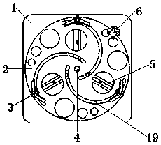
[0024] In the present invention, by rotating the cam turntable 2, the "T"-shaped nail 7 slides in the chute 19 of the cam turntable 2, and at the same time moves radially along the "T"-shaped groove guide rail 5. clamping.

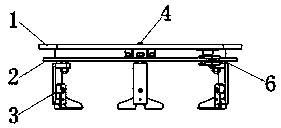
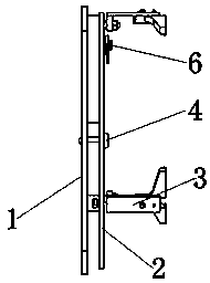
[0025] An adjustable workholding device (see Figure 1-Figure 3 and Figure 7 ), including a guide rail fixing plate 1 and a cam turntable 2, the cam turntable 2 is arranged on the guide rail fixing plate 1 and rotates through a central axis 4, and there are three “T”s arranged between the guide rail fixing plate 1 and the cam turntable Groove guide rail 5, the three "T" gro...


PUM


Abstract

The invention relates to an adjustable workpiece clamping device. Due to the adjustable workpiece clamping device, fast clamping of a workpiece can be facilitated, and by adjusting the caliber of hooks, workpieces in different calibers can be clamped easily and conveniently. According to the technical scheme, a guide rail fixing plate and a cam rotating disk are included; and the cam rotating diskis arranged on the guide rail fixing plate and rotates through a center shaft. The adjustable workpiece clamping device is characterized in that three T-shaped groove guide rails are arranged betweenthe guide rail fixing plate and the cam rotating disk, and are uniformly distributed at the center of the guide rail fixing plate in the circumferential direction; the included angle is 120 degrees,and three semicircular slide grooves are uniformly formed in the cam rotating disk; one end of each slide groove is arranged at the position close to the center of the cam rotating disk; the other endof each slide groove is arranged at the edge position of the cam rotating disk, and a hot wheel shape is formed; hook assemblies capable of sliding are connected to the T-shaped groove guide rails and the slide grooves; the cam rotating disk is locked through a locking assembly; and the locking assembly is arranged at the round edge position of the cam rotating disk.

Description

technical field [0001] The invention relates to an adjustable workpiece clamping device. Background technique [0002] With the rapid development of automation technology, the application of automatic clamping fixtures is becoming more and more common, but the known clamping fixtures have defects such as slow clamping speed and complex structure. [0003] When the existing clamps clamp the workpiece, it is often necessary to change the caliber of the clamper according to the size of the caliber of the workpiece, which requires a clamper capable of adjusting the clamping caliber to realize its function. At present, among the known fixtures, there is a lathe chuck three-jaw system that adjusts the clamping caliber through gears. The lathe chuck three-jaw system uses three screws to fasten the chuck to the machine tool through the screw holes on the end surface of the disc body. on the flange. Insert the wrench into the square hole of any gear, when the wrench is turned, the ...

Claims


Application Information

Patent Timeline
Patent Type & Authority Patents(China)
IPC IPC(8): B25B11/00B23Q3/00
CPCB23Q3/00B25B11/00
Inventor 蒋世磊向雪峰张锦孙国斌党小刚张强王震
Owner XIAN TECH UNIV
Features
  • Generate Ideas
  • Intellectual Property
  • Life Sciences
  • Materials
  • Tech Scout
  • Unparalleled Data Quality
  • Higher Quality Content
  • 60% Fewer Hallucinations
Learn More