Robot arm, nursing robot system and nursing method of system

A robot system and robotic hand technology, applied in the field of nursing robots, can solve problems such as difficult to meet the daily needs of home or hospital nursing, single function of nursing robots, etc.

Pending Publication Date: 2018-09-11
闫成山
View PDF0 Cites 8 Cited by
  • Summary
  • Abstract
  • Description
  • Claims
  • Application Information

AI Technical Summary

Problems solved by technology

[0004] The purpose of the present invention is to solve the problem that existing nursing robots have a single function and are difficult

Method used


Image

  • Robot arm, nursing robot system and nursing method of system
  • Robot arm, nursing robot system and nursing method of system
  • Robot arm, nursing robot system and nursing method of system

Examples


specific Embodiment approach 1

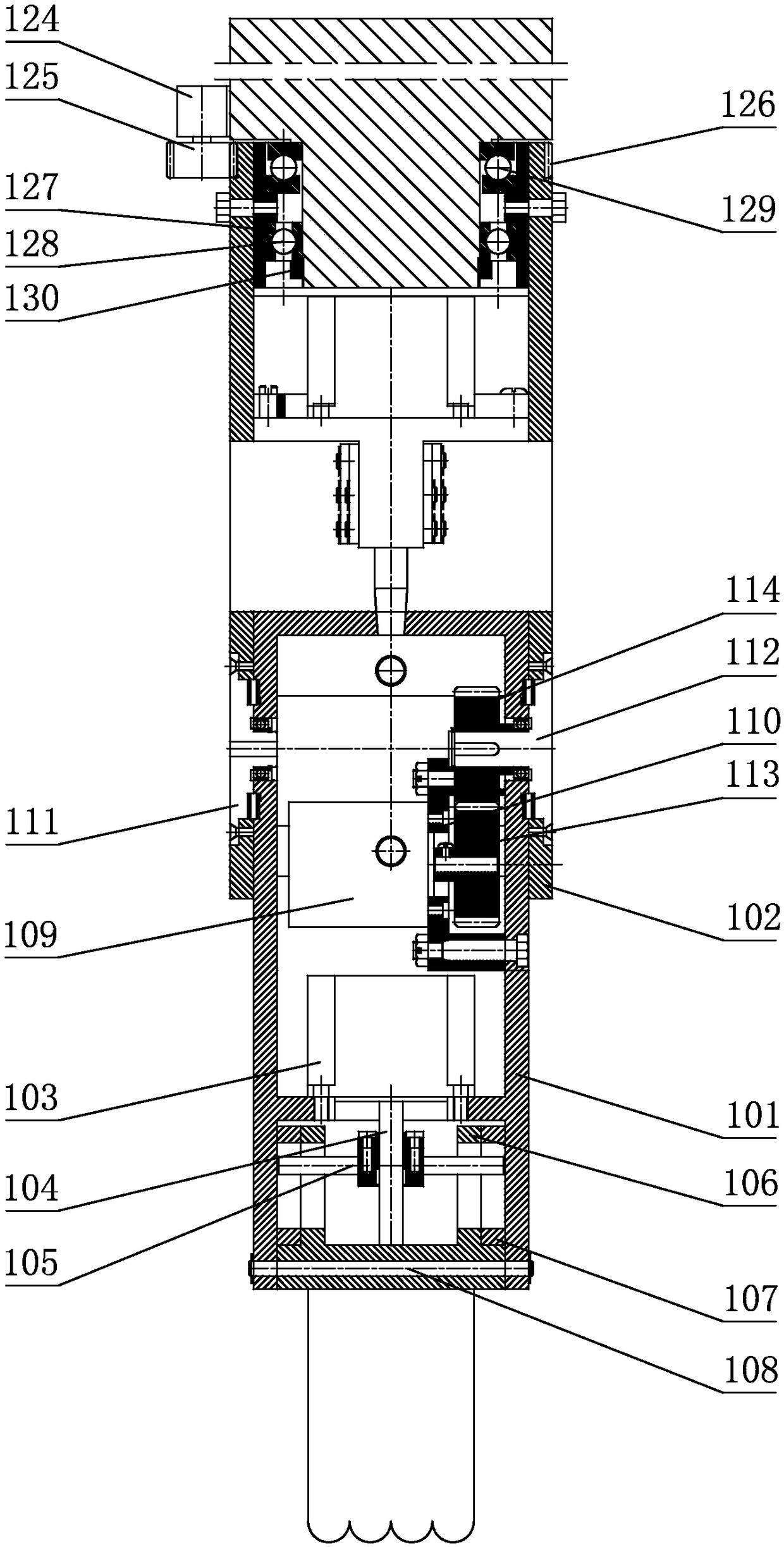
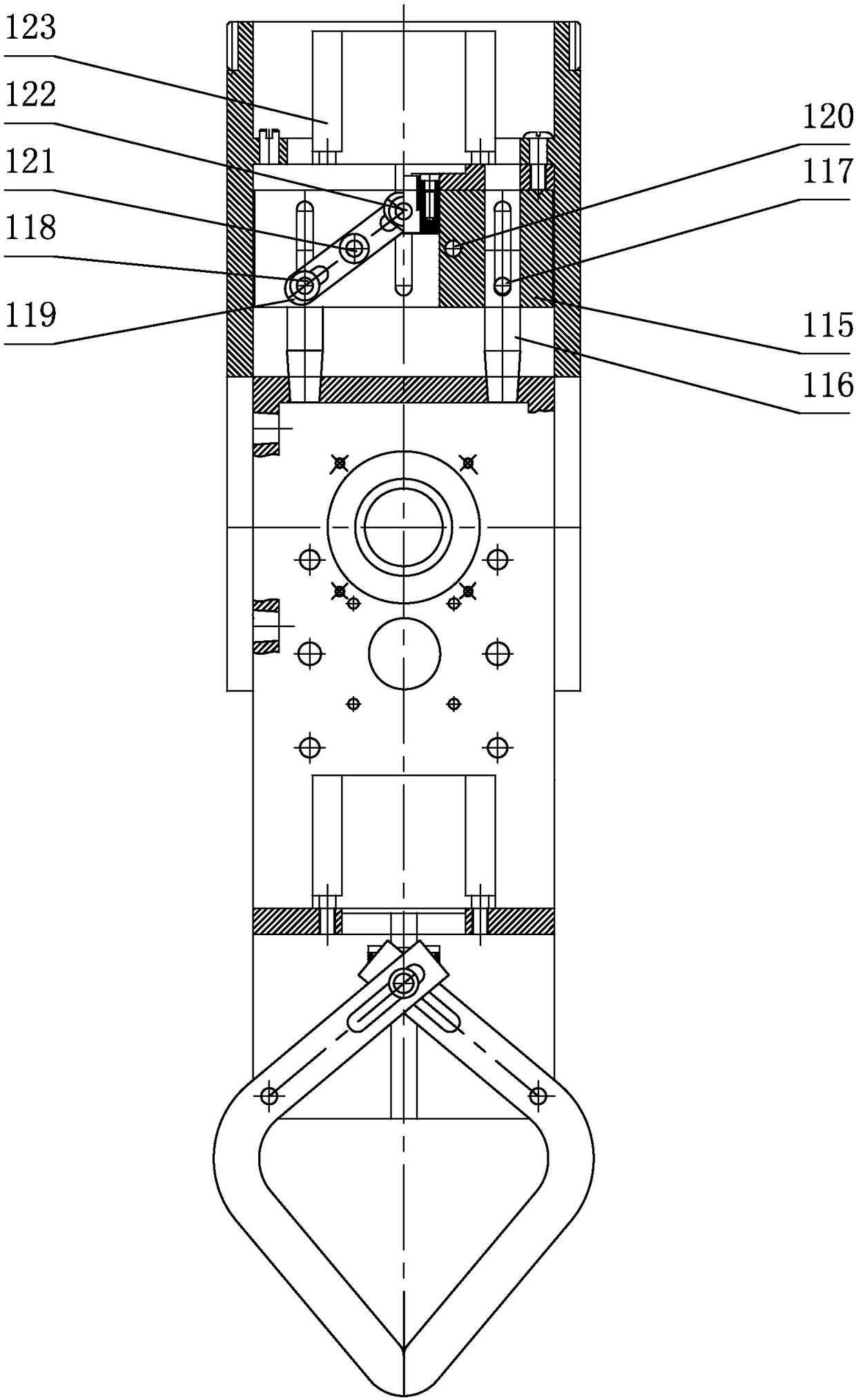
[0034] Specific implementation mode one: combine figure 1 with figure 2 Describe this embodiment, a robot hand for a nursing robot system in this embodiment, the robot hand for a nursing robot system includes an inner box body 101, an outer box body 102, a working assembly, an angular rotation assembly, a brake assembly and a horizontal The rotating assembly, the outer box body 102 and the inner box body 101 are hollow boxes, the lower end of the outer box body 102 is set on the inner box body 101, and the joint of the outer box body 102 and the inner box body 101 is provided with an angle rotation assembly, The inner box body 101 realizes the angular rotation through the angular rotation assembly and the outer box body 102, and the brake brake assembly is installed inside the outer box body 102, and the angular rotation assembly realizes the positioning between the inner box body and the outer box body through the brake brake assembly. The bottom of the inner box body 101 i...

specific Embodiment approach 2

[0035] Specific implementation mode two: combination figure 1 , figure 2 , Figure 11 to Figure 14 Describe this embodiment, the working assembly of this embodiment comprises working motor 103, working screw 104, gripper transmission shaft 105, thumb gripper 106, four-finger gripper 107 and gripper pin 108, and working motor 103 is fixedly installed on On the inner wall of the inner box body 101, the upper end of the working screw 104 is connected with the output shaft of the working motor 103, the gripper drive shaft 105 is fixed on the nut of the working screw 104, the middle part of the thumb gripper 106 and the four-finger gripper 107 The gripper pin shaft 108 is rotationally connected with the inner box body 101, and the tops of the thumb gripper 106 and the four-finger gripper 107 are respectively provided with gripper chutes for sliding engagement with the gripper transmission shaft 105, and the gripper transmission shaft 105 and The thumb gripper 106 and the four-fi...

specific Embodiment approach 3

[0036] Specific implementation mode three: combination figure 1 , figure 2 , Figure 7 to Figure 10Describe this embodiment, the angle rotation assembly of this embodiment includes angle rotation motor 109, angle rotation motor fixing frame 110, short semi-axis 111, long semi-axis 112, first driving gear 113 and first driven gear 114, angle rotation Motor fixed mount 110 is fixedly installed on the top inwall of inner box body 101, and angle rotation motor 109 is installed on the angle rotation motor fixed mount 110, and the first drive gear 113 is installed in the angle rotation motor 109 in angle rotation motor fixed mount 110 On the output shaft, the upper part of the inner box 101 is symmetrically provided with a shaft end passage hole for cooperating with the short semi-axis 111 and the long semi-axis 112, and the short semi-axis 111 and the long semi-axis 112 are coaxially arranged on the inner box 101 and the outer At the junction of the casing 102, the long half sha...


PUM


Abstract

The invention discloses a robot arm, a nursing robot system and a nursing method of the system, and relates to the field of nursing robots. The problems that an existing nursing robot is single in function, and daily needs of family or hospital nursing are hard to meet are solved. An inner box body is sleeved with the lower end of an outer box body of the robot arm for the nursing robot system, anangular rotating assembly is arranged at the connecting position of the outer box body and the inner box body, the inner box body and the outer box body achieve angular rotation through the angular rotating assembly, a brake assembly is arranged in the outer box body, the angular rotation assembly achieves positioning between the inner box body and the outer box body through the brake assembly, awork assembly is arranged on the lower portion of the inner box body, the inner box body achieves nursing action of a nursing person through the work assembly, a horizontal rotating assembly is arranged on the upper portion of the outer box body, and the outer box body achieves horizontal rotation through the horizontal rotating assembly and the Z coordinates of the robot. The daily needs of family or hospital nursing can be met.

Description

technical field [0001] The invention relates to the technical field of nursing robots, in particular to a robotic hand, a nursing robot system and a nursing method thereof. Background technique [0002] With the aggravation of our country's aging degree and the invasion of chronic diseases, many elderly people are in a state of inconvenient walking or semi-disability. The support and care of the elderly has become an important issue that the society has to face. Young people usually need to work outside for a long time to support their families, and have little time to care for the elderly. The increase in labor costs makes the burden of family care more and more heavy. For the caregivers, the daily life is greatly restricted, including turning over, putting on and taking off diapers, defecating, and showering, all of which require nursing staff to take care of them. cause some damages. For nurses, high-intensity nursing work brings greater nursing difficulties, especially...

Claims


Application Information

Patent Timeline
IPC IPC(8): B25J11/00B25J9/12B25J15/02B25J19/00A61G7/14A61G5/00
CPCA61G5/00A61G7/1025A61G7/1034A61G7/1046B25J9/102B25J9/109B25J9/126B25J11/009B25J15/0206B25J19/0004A61G2203/12
Inventor 闫成山
Owner 闫成山
Why Eureka
Try Eureka