
Structurally strengthened tent skeleton and center reinforcing structure thereof

A center reinforcement and tent technology, applied in the field of tents, can solve problems such as inconvenient installation and maintenance, unstable tent skeleton, complex installation structure, etc., and achieve the effects of increased strength, reduced number of connections, and high skeleton stability

Pending Publication Date: 2018-09-11
ZHEJIANG JASAN LEISURE PROD
View PDF1 Cites 3 Cited by
  • Summary
  • Abstract
  • Description
  • Claims
  • Application Information

AI Technical Summary

Problems solved by technology

With the above-mentioned structure, since each tie rod and frame support rod needs to be connected with the chassis during installation, on the one hand, the chassis will be thin and the tent frame will be unstable; on the other hand, the installation structure is complicated, and installation and maintenance are inconvenient

Method used


Image

  • Structurally strengthened tent skeleton and center reinforcing structure thereof
  • Structurally strengthened tent skeleton and center reinforcing structure thereof
  • Structurally strengthened tent skeleton and center reinforcing structure thereof

Examples


Embodiment 1

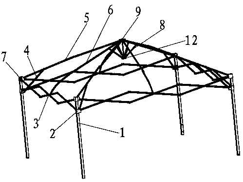
[0027] Such as figure 1 with 2 As shown, a structure-reinforced tent frame includes four columns 1, and the column 1 is provided with a connecting seat 7 and a sliding seat 2, wherein the connecting seat 7 is fixed on the top of the column 1, and the sliding seat 2 is sleeved on the column 1 The upper column can slide relative to the column 1. The connecting base 7 is hinged with the first tarpaulin strut 5 , and the other end of the first tarpaulin strut 5 is hinged with the upper disc seat 9 . An auxiliary support rod 4 is also hinged on the first tarpaulin strut 5 , and the other end of the auxiliary support rod 4 is hinged to the sliding seat 2 . The first tarpaulin strut 5 is composed of two or more than two struts hinged. The sliding seat 2 slides, and the auxiliary support rod 4 is pulled, so that the first tarpaulin strut 5 is pulled to be folded.

[0028] A hinge beam 3 is arranged between adjacent columns 1 , and each end of the hinge beam 3 is respectively conne...

Embodiment 2

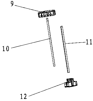
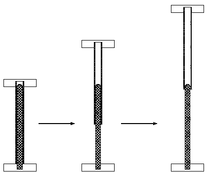
[0037] Such as Figure 5As shown, the present invention also provides a central reinforcement structure of a structurally reinforced tent skeleton, which structure includes a first tarpaulin strut 5, a second tarpaulin strut 6, a support rod 8, an upper plate seat 9 and a lower plate Seat 12. There are four first tarpaulin struts 5 and second tarpaulin struts 6 respectively. Both the first tarpaulin strut 5 and the second tarpaulin strut 6 are hingedly fitted with the upper disc seat 9 . Among them, four second tarpaulin struts 6 and any two first tarpaulin struts 5 at any diagonal are connected to the support rods 8, and the other end of the support rods 8 is hinged to the lower disc seat 12, the lower disc seat 12 and the upper disc seat 9 telescopic limit rods are set. The structure of the telescopic limit rod is as described in Embodiment 1, and will not be repeated here.

[0038] The central reinforcement structure uses the telescopic limit rod to control the opening ...


PUM


Abstract

The invention discloses a structurally strengthened tent skeleton and a center reinforcing structure thereof. The tent skeleton comprises upright columns, connecting bases and sliding bases are arranged on the upright columns, first tarpaulin supporting rods are hinged to the connecting bases, the other ends of the first tarpaulin supporting rods are hinged to an upper disc base, auxiliary supporting rods are hinged to the first tarpaulin supporting rods, the other ends of the auxiliary supporting rods are hinged to the sliding bases, hinge beams are arranged between the adjacent upright columns, each end of the hinge beams is respectively connected with the connecting bases and the sliding bases on the upright columns, second tarpaulin supporting rods are hinged to the hinge points of thehinge beams, the other ends of the second tarpaulin supporting rods are hinged to the upper disc base, four second tarpaulin supporting rods and any one of two diagonal first tarpaulin supporting rods are connected with supporting rods, the other ends of the supporting rods are hinged to a lower disc base, and a telescopic limit rod is arranged between the lower disc base and the upper disc base.According to the tent skeleton, the telescopic limit rod is arranged between the upper disc base and the lower disc base to ensure that the top of the tent skeleton is not tilted when the tent skeleton is folded or unfolded, and the skeleton stability is high.

Description

technical field [0001] The invention belongs to the technical field of tents, and in particular relates to a structure-reinforced tent frame and a central reinforcement structure thereof. Background technique [0002] A tent is an indispensable outdoor product in people's daily life, and it usually includes a support frame and a tarpaulin. In order to be easy to carry, the support frame is usually designed as a foldable skeleton structure. [0003] The utility model patent with the notification number CN205918220U discloses a kind of anti-water tent skeleton, which includes foot poles, hinged beams, skeleton support rods and top plates. One end is hinged, the other end of the skeleton support rod is connected to the top plate, and the top between two adjacent foot rods is connected by a hinge beam; it is characterized in that it also includes a pull rod and top plate support rod assembly, and one end of the pull rod is connected to the top plate Hinged, the other end is hin...

Claims


Application Information

Patent Timeline
IPC IPC(8): E04H15/50
CPCE04H15/50
Inventor 孙渊儒颜家璐何健
Owner ZHEJIANG JASAN LEISURE PROD
Learn More