High-flow dynamic output control method of cartridge valve and cartridge valve

A technology of dynamic output and control method, which is applied in the direction of fluid pressure actuators, servo motor components, mechanical equipment, etc., and can solve the problem that the dynamic output flow rate of pressure liquid is small, increases, and cannot meet the energy supply and control stability of large hydraulic pile drivers demand and other issues

Active Publication Date: 2018-09-11
GUANGDONG LIYUAN HYDRAULIC MACHINERY
View PDF8 Cites 8 Cited by
  • Summary
  • Abstract
  • Description
  • Claims
  • Application Information

AI Technical Summary

Problems solved by technology

[0007] In view of the above-mentioned deficiencies in the prior art, the purpose of the present invention is to provide a new large-flow dynamic output control method for cartridge valves, so as to solve the problem that the dynamic output flow rate of the pressure liquid of the existing cartridge valves is small and cannot meet the requirements of 1000-2000 tons. and the above large-scale hydraulic pile driver energy supply and control stability requirements; at the same time, a large-flow dynamic output cartridge valve is provided to implement the above method, which through the design of the double-flow curve structure, through the first oil outlet, the second The mutual cooperation between the oil outlet, the third oil outlet and the valve core realizes the purpose of controlling the large flow of hydraulic oil to enter and exit the valve body cavity dynamically, increasing the flow rate of the cartridge valve per unit time and improving the stability of the flow rate, so as to Meet the power and control requirements of large pile drivers of 1000-2000 tons and above

Method used


Image

  • High-flow dynamic output control method of cartridge valve and cartridge valve
  • High-flow dynamic output control method of cartridge valve and cartridge valve
  • High-flow dynamic output control method of cartridge valve and cartridge valve

Examples


Embodiment 1

[0044] Example 1: See attached Figure 1-3 , the method for controlling the dynamic output of a cartridge valve with a large flow rate provided by the present invention comprises the following steps:

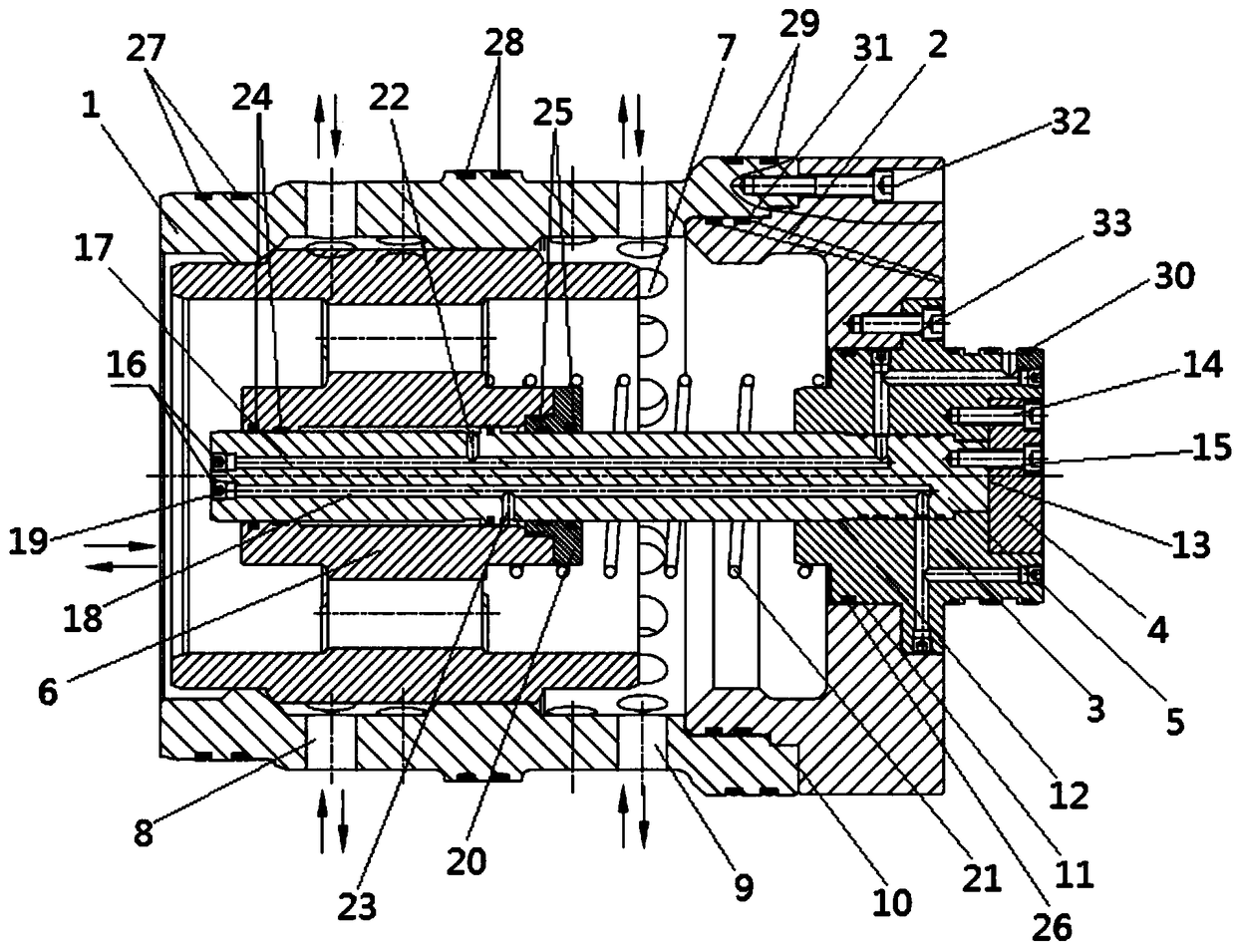
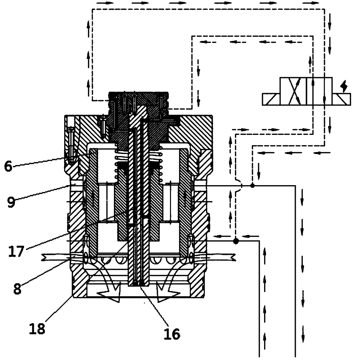
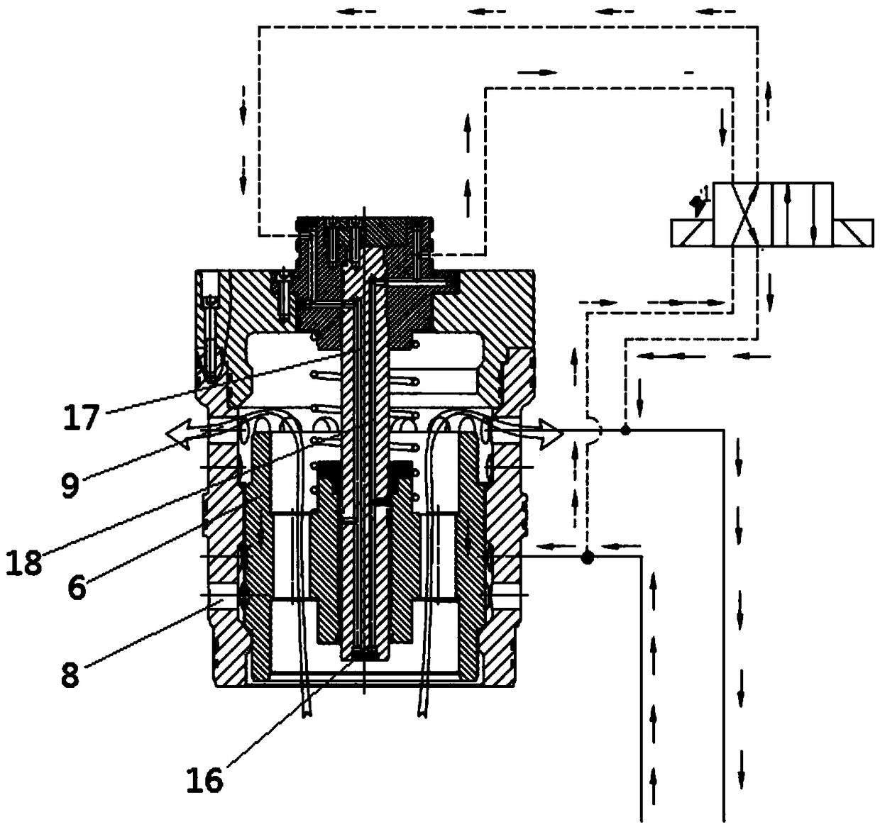
[0045] (1) A cartridge valve, a control solenoid valve, a hydraulic pump and an oil return tank are provided; the cartridge valve includes a valve sleeve 1; the control solenoid valve includes DT1 oil circuit and DT2 oil circuit;

[0046] (2) A number of oil outlet holes 7 with the same shape, orderly arrangement and equal size are set on the valve sleeve 1. The oil outlet hole 7 is composed of the first oil outlet 8 and the second oil outlet 9. The inside of the valve sleeve 1 is provided with a cavity;

[0047] (3) Set a valve sleeve end cover 2 on the valve sleeve 1, set a guide shaft fixing seat 3 on the valve sleeve end cover 2, set a guide shaft 5 on the guide shaft fixing seat 3, and set a valve core on the guide shaft 5 6. The guide shaft 5 is located inside the cavity...


PUM


Abstract

The invention discloses a high-flow dynamic output control method of a cartridge valve. The high-flow dynamic output control method of the cartridge valve comprises the steps that a DT2 oil path of acontrol solenoid valve is through while a DT1 oil path of the control solenoid valve is stopped, hydraulic oil inside a first oil conveying channel passes through the DT2 oil path to return to an oiltank so that a guide shaft can provide power for a valve element sleeving the guide shaft, and thus the valve element is driven to move upwards; the DT1 oil path of the control solenoid valve is through while the DT2 oil path of the control solenoid valve is stopped, hydraulic oil inside a second oil conveying channel passes through the DT1 oil path to return to the oil tank so that the guide shaft can provide supporting power for the valve element, and thus the valve element is driven to move downwards; a second oil outlet communicates with a third oil outlet, and hydraulic oil inside the third oil outlet is discharged out from the second oil outlet. The invention further provides the high-flow dynamic output cartridge valve for implementation of the method. By increasing the flow of thecartridge valve and improving flow stability, the requirements of providing sufficient power and stable control for large piling machines of 1000 tons or above.

Description

technical field [0001] The invention relates to the technical field of hydraulic piling equipment, in particular to a method for controlling the large-flow dynamic output of a cartridge valve and the cartridge valve. Background technique [0002] Common pile drivers in construction engineering include hydraulic walking diesel hammer pile drivers and high-frequency hydraulic vibration pile drivers. With the progress of society and the continuous improvement of the level of science and technology, it also drives the continuous improvement of the technical level of the construction field. At present, my country's large-scale hydraulic pile drivers are still in the development stage, and the technology is not yet mature. It is imported from abroad, and imported equipment cannot meet the current demand for large-scale hydraulic pile drivers in our construction field, which is not conducive to the development of my country's construction field. Therefore, we urgently need to improv...

Claims


Application Information

Patent Timeline
Patent Type & Authority Applications(China)
IPC IPC(8): F15B13/02
CPCF15B13/021
Inventor 莫朝卿魏智健
Owner GUANGDONG LIYUAN HYDRAULIC MACHINERY
Why Eureka
Try Eureka