Device for real-time and high-precision monitoring of direction of laser-range finding light beam

A technology of beam pointing and laser ranging, which is applied in the direction of radio wave measurement systems and instruments, can solve the problems of increasing the difficulty of real-time and high-precision monitoring of laser beams, the difficulty of adjusting parallelism, and the impact of damage to the receiving system, so as to reduce damage Risk, improved aiming, high-precision real-time parallel effects

Active Publication Date: 2018-09-11
SHANGHAI ASTRONOMICAL OBSERVATORY CHINESE ACAD OF SCI
View PDF6 Cites 3 Cited by
  • Summary
  • Abstract
  • Description
  • Claims
  • Application Information

AI Technical Summary

Problems solved by technology

However, it is mentioned in the article that it is difficult to overlap two beams of different colors, and it is difficult to adjust the parallelism to within ±15 arcseconds; the follow-up uses laser emission to adjust and monitor at low energy to avoid narrow-band filtering in the eyes and the receiving system. Due to the damage of the light sheet and photomultiplier tube, there is a certain deviation between the direction of the low-power las...

Method used


Image

  • Device for real-time and high-precision monitoring of direction of laser-range finding light beam
  • Device for real-time and high-precision monitoring of direction of laser-range finding light beam
  • Device for real-time and high-precision monitoring of direction of laser-range finding light beam

Examples


Embodiment Construction

[0023] The present invention will be described in further detail below through specific embodiments and in conjunction with the accompanying drawings.

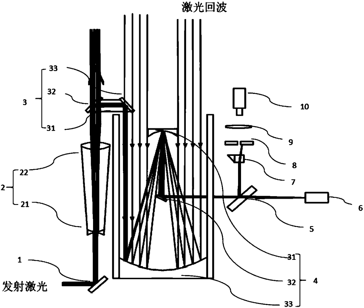
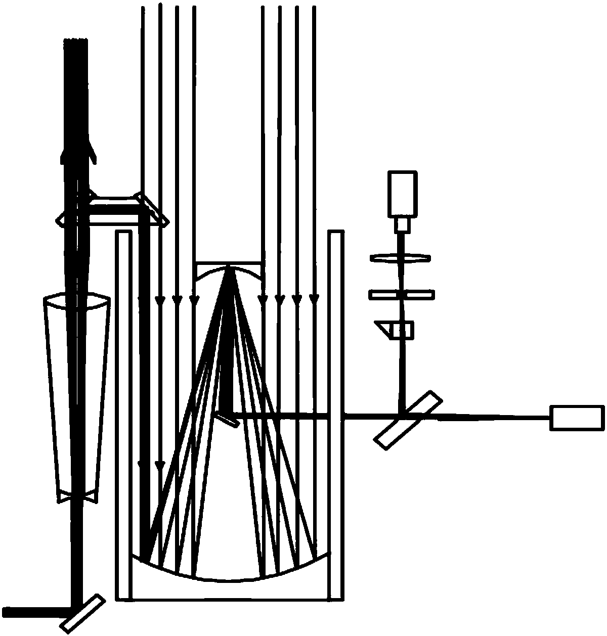
[0024] Such as figure 1 Shown is a method for real-time high-precision monitoring of laser ranging beam pointing according to an embodiment of the present invention, including a 45° reflector 1 along the direction of the emitting laser light path, a transmitting telescope 2, a right-angle reflecting combination mirror 3, a receiving Telescope 4, beam splitter 5, monitoring CCD 6, acousto-optic modulator 7, controllable aperture diaphragm 8, collimating mirror 9, detector 10.

[0025] The emitted laser light is reflected by the 45° reflector 1 and passes through the transmitting telescope 2 to the right-angle reflective combination mirror 3. Most of the laser light passes through the right-angle reflective combination mirror 3, and part of the laser light is antiparallel to the emitted laser through the right-angle reflective c...


PUM


Abstract

The invention relates to a device for the real-time and high-precision monitoring of the direction of a laser-range finding light beam, and the device comprises a 45-degree reflector, a transmitting telescope, a right-angle combined reflector, a receiving telescope, a beam splitter, a monitoring CCD, an acousto-optic modulator, a controllable small aperture diaphragm, a collimating mirror, and a detector. Transmitted laser is transmitted by the transmitting telescope, wherein most of the laser passes through the right-angle combined reflector on a transmitting light path, and a part of laser is reflected by the right-angle combined reflector, and is transmitted in an opposite direction in a manner of being parallel to the transmitting light path to the receiving telescope to reach the beamsplitter. A small part of laser passes through the beam splitter to be detected by the monitoring CCD, and other parts of laser are reflected. When the acousto-optic modulator works, a reflecting light beam deflects to the edge of the controllable small aperture diaphragm, thereby avoiding the damages caused by light to the detector. When the acousto-optic modulator is not in a working state, a laser echo is enabled to pass through the controllable small aperture diaphragm and the collimating mirror to reach the detector. The real-time monitoring of the direction of the light beam facilitatesthe real-time collimation of a detection target in the laser range finding, and promotes the development of the laser range finding, especially the satellite laser range finding.

Description

technical field [0001] The invention relates to the field of laser ranging, in particular to a device for real-time monitoring of laser ranging beam pointing. Background technique [0002] Laser ranging has excellent characteristics such as high precision and long ranging distance, and is widely used in the position measurement of space objects such as satellites and space debris. Artificial satellites are widely used in communication, scientific survey and experiment, military defense, meteorology and other fields. The global positioning system GPS and my country's Beidou positioning system have been widely used in people's social activities and life, and have profoundly changed people's way of life. , to promote human development. At the same time, in the process of human beings exploring space, more and more artificial satellites and deep space probes have been launched into space. In the harsh space environment of high radiation, vacuum, and zero gravity, these human-ma...

Claims


Application Information

Patent Timeline
IPC IPC(8): G01S7/497G01S7/481
CPCG01S7/481G01S7/497
Inventor 龙明亮程志恩汤凯邓华荣吴志波秦思张忠萍
Owner SHANGHAI ASTRONOMICAL OBSERVATORY CHINESE ACAD OF SCI
Why Eureka
Try Eureka