Eureka AIR delivers breakthrough ideas for toughest innovation challenges, trusted by R&D personnel around the world.

Two-dimensional holographic projection display method and system

A display method and two-dimensional holographic technology, applied in the field of projection display, can solve the problems of unsuitable viewing habits, waste of computing resources and spatial bandwidth product of spatial light modulators, etc., and achieve the effect of avoiding waste and avoiding waste of spatial bandwidth product.

Active Publication Date: 2019-11-05
BOE TECH GRP CO LTD
View PDF4 Cites 0 Cited by
  • Summary
  • Abstract
  • Description
  • Claims
  • Application Information

AI Technical Summary

Problems solved by technology

The pixels of existing spatial light modulators are generally arranged at two-dimensional equidistant intervals, so the image area formed on the imaging surface is square, and the available modulation area of ​​the spatial light modulator itself is generally rectangular (for example, the more typical spatial light modulation The device has a rectangular modulation area with a resolution of 16:9), which will cause oversampling in the direction of the long side when applied to a square display, resulting in a waste of computing resources and the spatial bandwidth product of the spatial light modulator
In addition, human vision is more accustomed to viewing rectangular image areas, and the square image area formed by holographic projection is not suitable for human viewing habits.

Method used


Image

  • Two-dimensional holographic projection display method and system
  • Two-dimensional holographic projection display method and system
  • Two-dimensional holographic projection display method and system

Examples


Embodiment Construction

[0024] Embodiments of the present invention are described in detail below, and examples of the embodiments are shown in the drawings, wherein the same or similar reference numerals denote the same or similar elements or elements having the same or similar functions throughout. The embodiments described below by referring to the figures are exemplary and are intended to explain the present invention and should not be construed as limiting the present invention.

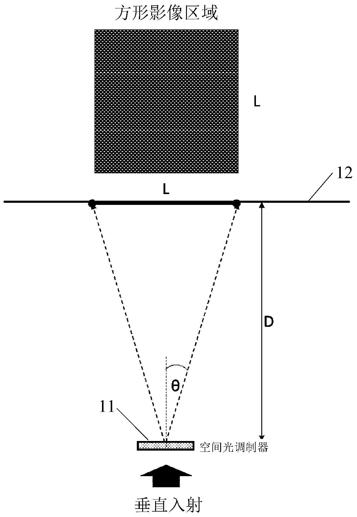
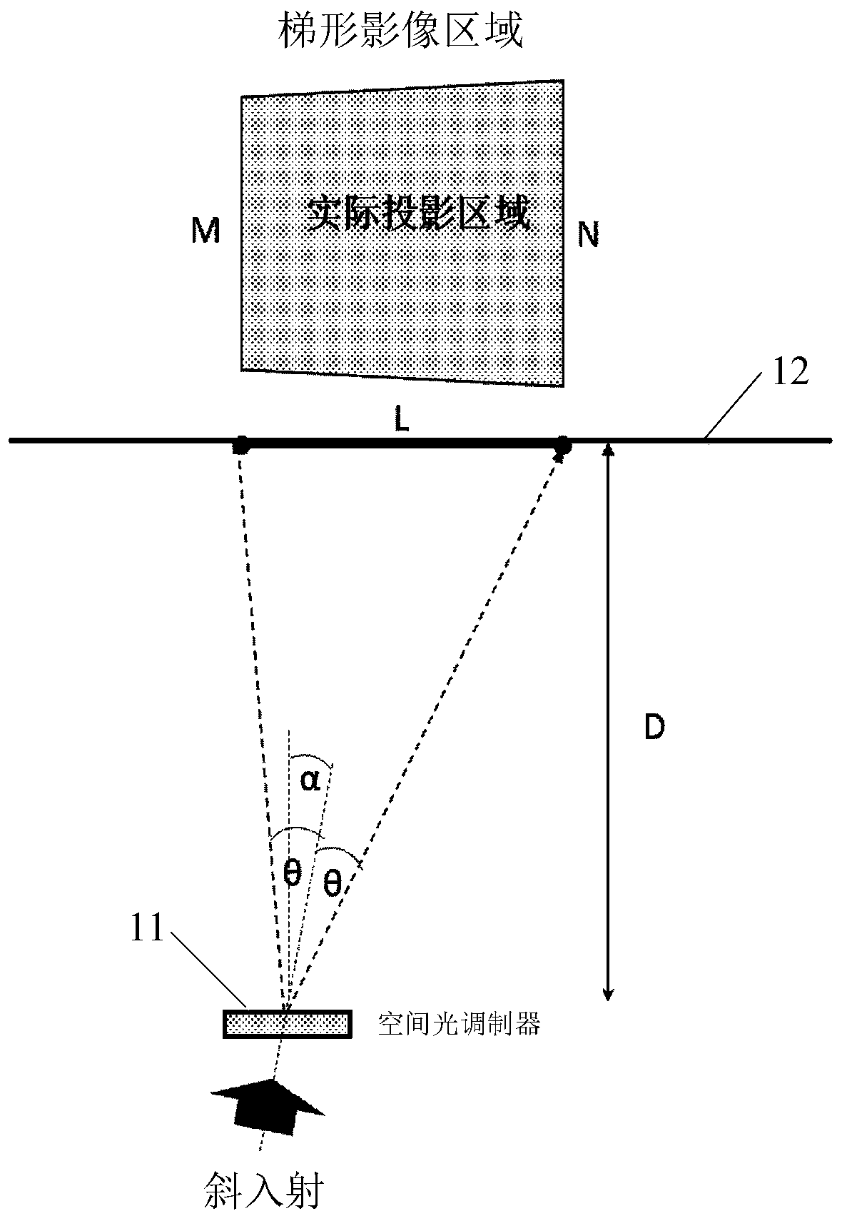
[0025] In order to clearly illustrate the two-dimensional holographic projection display method and system of the embodiments of the present invention, the geometric relationship of the two-dimensional holographic projection will be described in detail below.

[0026] figure 1 It is a schematic diagram of the geometric relationship of the two-dimensional holographic projection when the parallel light beam is vertically incident on the spatial light modulator. Such as figure 1 As shown, when the parallel light beam is...


PUM


Abstract

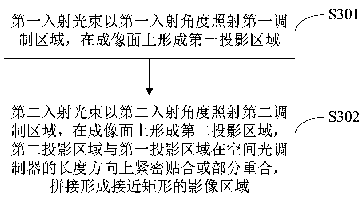
The present invention proposes a two-dimensional holographic projection display method and system, wherein the two-dimensional holographic projection display method includes: the spatial light modulator is divided into a first modulation area and a second modulation area in the length direction, and the first incident light beam is An incident angle irradiates the first modulation area to form a first projection area on the imaging plane; a second incident light beam irradiates the second modulation area at a second incident angle to form a second projection area on the imaging plane, The second projection area and the first projection area are closely attached or partially overlapped in the length direction of the spatial light modulator, and are spliced ​​to form a nearly rectangular image area. The two-dimensional holographic projection display method and system proposed by the present invention avoid the waste of computing resources and the spatial bandwidth product of the spatial light modulator, and can form an image area suitable for people's viewing habits.

Description

technical field [0001] The present invention relates to the technical field of projection display, in particular to a two-dimensional holographic projection display method and system. Background technique [0002] Most of the two-dimensional holographic projection devices based on phase modulation devices are based on the fast Fourier transform algorithm. Since the fast Fourier transform algorithm itself implies sampling restrictions on the spatial domain and the frequency domain, there is a strict correspondence between the frequency domain and the spatial domain. In two-dimensional holographic projection, the imaging plane is a spatial plane, and the spatial light modulator is a frequency domain plane. A two-dimensional image is obtained on the surface. [0003] Limited by the Fourier transform relationship, the size of the imaging area is only determined by the pixel pitch a of the spatial light modulator, and has nothing to do with the size of the available area of ​​th...

Claims


Application Information

Patent Timeline
Patent Type & Authority Patents(China)
IPC IPC(8): G03H1/22G03B21/00
CPCG03B21/005G03H1/2294G03H2210/20G03H1/2286G03H2001/2223G03H2222/34G03H2001/2218G03B35/18G02B5/32G03H1/0841G03H1/2205G03H2001/2207G03H2223/19
Inventor 石炳川
Owner BOE TECH GRP CO LTD
Why Eureka
Eureka Blog
Learn More