Plastic separation equipment

A sorting and plastic technology, applied in the direction of solid separation, separation of solids from solids with airflow, and filtration, etc., can solve problems such as easy blockage of screens and easy accumulation of plastic particles, so as to enhance screening quality, prevent accumulation, The effect of improving screening efficiency

Inactive Publication Date: 2018-09-14
宁波隆锐机械制造有限公司
View PDF0 Cites 9 Cited by
  • Summary
  • Abstract
  • Description
  • Claims
  • Application Information

AI Technical Summary

Problems solved by technology

[0003] The purpose of the present invention is to provide a plastic sorting equipment to solve the p...

Method used


Image

  • Plastic separation equipment

Examples


Embodiment Construction

[0020] Further detailed explanation through specific implementation mode below:

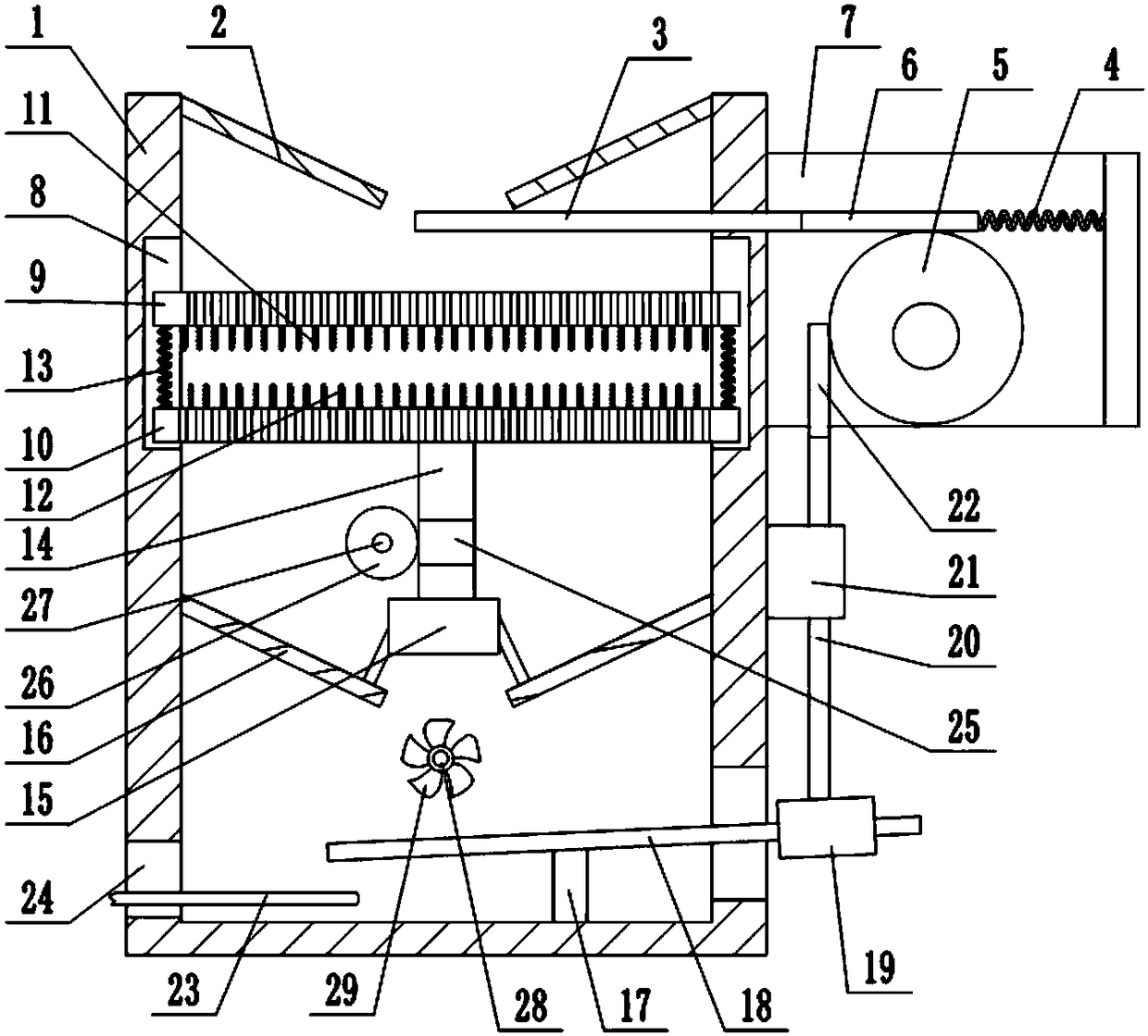
[0021] The reference signs in the drawings of the description include: housing 1, feed port 2, sealing plate 3, reciprocating spring 4, gear 5, tooth portion 6, connecting plate 7, annular groove 8, first screen 9, second Screen 10, first push piece 11, second push piece 12, connection spring 13, connection shaft 14, motor 15, discharge port 16, support column 17, swing rod 18, slider 19, slide rod 20, guide rail 21 , rack 22, conveyor 23, through hole 24, worm screw 25, worm wheel 26, first rotating shaft 27, second rotating shaft 28, rotating blade 29.

[0022] The embodiment is basically as attached figure 1 Shown:

[0023] The plastic sorting equipment mainly consists of a housing 1, a feed port 2, a control unit, a discharge port 16, a first screen 9, a second screen 10, a first pusher 11, a second pusher 12, a connecting spring 13. Drive device, connecting shaft 14, conveyor 23 constitut...


PUM


Abstract

The invention relates to the field of plastic particle screening, and discloses plastic separation equipment. The equipment comprises a shell, the top of the shell is provided with a material inlet, the bottom of the shell is provided with a material outlet, and the shell is provided with a regulation and control unit capable of adjusting the opening size of the material inlet according to the discharge quantity of the material outlet; an inner wall of the shell is provided with a circumferential groove into which a first screen and a second screen are rotationally connected, the meshes of thefirst screen and the meshes of the second screen are mutually staggered in positions, the bottom of the first screen is provided with a first pushing part which matches with the meshes of the secondscreen, and the top of the second screen is provided with a second pushing part which matches with the meshes of the first screen; the bottom of the second screen is connected with a connecting shaft,and one end, which is far away from the second screen, of the connecting shaft is connected with a driving device. According to the scheme, the feeding quantity of the material inlet can be adjustedaccording to the discharging condition of plastic particles so as to prevent the phenomenon that the screens are easy to damage as excessive load bearing appears, the meshes can be prevented from being blocked, and the screening efficiency of the plastic particles is further improved.

Description

technical field [0001] The invention belongs to the field of plastic screening. Background technique [0002] In the production process of plastic particles, due to the randomness of the crushing of plastic particle crushers, it cannot be guaranteed that the size specifications of all the crushed plastic particles can be within the standard range. The plastic particles are screened. When the traditional three-dimensional layered screening machine is in use, plastic particles often accumulate on the screen due to the large flow of plastic particles, resulting in a decrease in screening efficiency, which greatly affects the production efficiency of plastic products. In addition, the accumulation of plastic particles on the screen will also easily lead to blockage of the screen mesh, further reducing the screening efficiency of plastic particles. Contents of the invention [0003] The object of the present invention is to provide a plastic sorting device to solve the proble...

Claims


Application Information

Patent Timeline
IPC IPC(8): B07B9/00B07B1/36B07B1/50B07B4/02B02C23/14B02C23/16B02C23/20
CPCB07B9/00B02C23/14B02C23/16B02C23/20B02C2023/165B07B1/36B07B1/50B07B4/02B07B2201/04
Inventor 李新平
Owner 宁波隆锐机械制造有限公司
Why Eureka
Try Eureka