Self-advancing and self-rotating shield machine grouting channel high-pressure dredging device and system

A grouting channel and self-rotating technology, which is applied in the direction of cleaning hollow objects, cleaning methods and utensils, chemical instruments and methods, etc., can solve the problems of inaccessibility of people and tools, improper parameter setting, and long distance between the grout inlet and the grout outlet to reduce the risk of secondary clogging, ensure speed and efficiency, and reduce the effect of slurry sag

Pending Publication Date: 2018-09-14
中铁工程装备集团盾构制造有限公司
View PDF24 Cites 3 Cited by
  • Summary
  • Abstract
  • Description
  • Claims
  • Application Information

AI Technical Summary

Problems solved by technology

[0002] At present, a large number of shield tunneling methods are used in tunnel engineering in my country. A large number of shield tunneling machines introduced in my country in the early stage are dual-liquid synchronous grouting systems. In the process of use, water glass is used as a rapid coagulant. Short, the mixing mechanism of cement slurry and water glass is located at the outlet end, and due to the laying of pipe tiles, the distance between the slurry inlet and the slurry outlet is relatively long, and the pipes in the double-pipeline setting are curved with a small radius, so people and tools cannot Close, although a high-pressure backflushing system is installed, due to human operation or improper system parameter setting, after the two liquids are mixed, they will quickly semi-solidify or solidify into cement blocks, blocking the outlet, making the equipment unable to use normally, and even causing shutdowns. Major accident
At present, artificial knocking and vibration outside the shell, dredging of steel bars or stirring of flexible shafts are used, but the blocked grouting pipelines cannot be completely cleaned, and the shield machine has to work for a long time.

Method used


Image

  • Self-advancing and self-rotating shield machine grouting channel high-pressure dredging device and system
  • Self-advancing and self-rotating shield machine grouting channel high-pressure dredging device and system
  • Self-advancing and self-rotating shield machine grouting channel high-pressure dredging device and system

Examples


Embodiment Construction

[0021] The specific implementation manners of the present invention will be described in detail below in conjunction with the accompanying drawings.

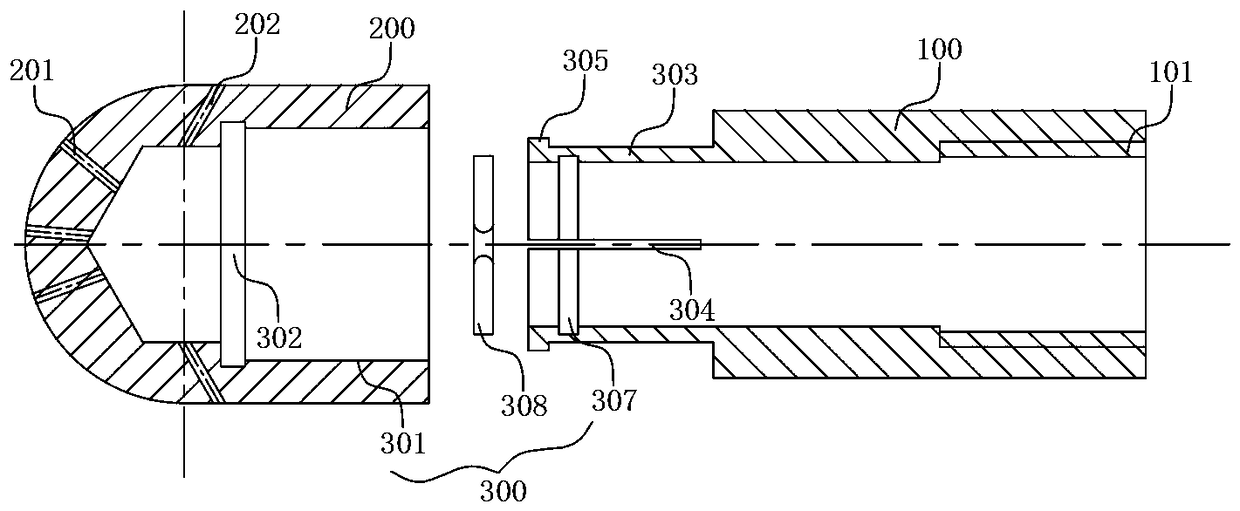
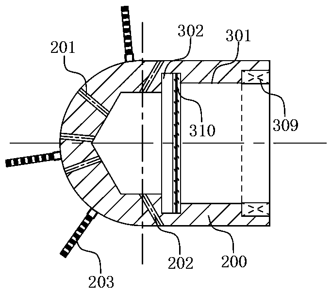
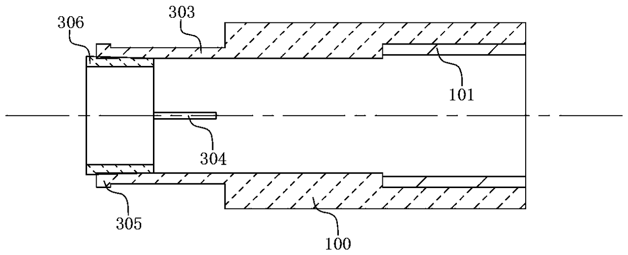
[0022] see Figure 1-Figure 3 , a self-propelled, self-rotating shield machine grouting channel high-pressure dredging device of the present invention, comprising a connecting cylinder 100 and a rotating nozzle 200, the rotating nozzle 200 is coaxially arranged with the connecting cylinder 100, and the rotating nozzle and the connecting cylinder A rotating connection assembly 300 is arranged between them, and the rotating nozzle 200 is connected to the end of the connecting cylinder 100 through the rotating connecting assembly 300, and can rotate relative to the connecting cylinder 100; wherein, the rotating nozzle 200 is sealed at the front end, and the rear end is connected to the A columnar hollow structure connected to the cylinder. The rotary nozzle 200 is provided with at least two front nozzle holes 201 and at least two r...


PUM


Abstract

The invention belongs to the technical field of dredging and cleaning the grouting channel of a shield machine tail shield, and relates to a self-advancing and self-rotating shield machine grouting channel high-pressure dredging device. The self-advancing and self-rotating shield machine grouting channel high-pressure dredging device comprises a connecting cylinder body and a rotating spray head,wherein the rotating spray head is coaxially arranged with the connecting cylinder body, and a rotating connecting assembly is arranged between the rotating spray head and the connecting cylinder body; the rotating spray head is a cylindrical hollow structure with a sealed front end and a rear end communicating with the connecting cylinder body; and at least two front spray holes and at least tworear spray holes are formed in the rotating spray head. According to the self-advancing and self-rotating shield machine grouting channel high-pressure dredging device, the tail shield grouting channel of a shield machine is cut and cleaned by high-pressure water without adding any chemical materials, thereby having great positive significance for protecting the environment. In addition, groutingchannels are mostly curved channels with small radius, the self-advancing and self-rotating shield machine grouting channel high-pressure dredging device can thoroughly clean all solidified slurry inthe channels, reduce the slurry sagging, shorten the shutdown time, and ensure the speed and benefit of tunnel excavation.

Description

technical field [0001] The invention belongs to the technical field of dredging and cleaning the grouting channel of the tail shield of a shield machine, and in particular relates to a high-pressure dredging device and system for a self-advancing and self-rotating shield machine grouting channel. Background technique [0002] At present, a large number of shield tunneling methods are used in tunnel engineering in my country. A large number of shield tunneling machines introduced in my country in the early stage are dual-liquid synchronous grouting systems. In the process of use, water glass is used as a rapid coagulant. Short, the mixing mechanism of cement slurry and water glass is located at the outlet end, and due to the laying of pipe tiles, the distance between the slurry inlet and the slurry outlet is relatively long, and the pipes in the double-pipeline setting are curved with a small radius, so people and tools cannot Close, although a high-pressure backflush system is...

Claims


Application Information

Patent Timeline
Patent Type & Authority Applications(China)
IPC IPC(8): B08B9/032
CPCB08B9/0321B08B2209/032
Inventor 李永军李楠李宁员元姣杨宗良
Owner 中铁工程装备集团盾构制造有限公司
Why Eureka
Try Eureka