Method for forming pipe fitting with internal high pressure and external low pressure and forming machine

A low-pressure forming and internal high-pressure technology, applied in the field of pipe fittings production equipment, can solve the problems of high weld quality requirements, reduce the proportion of forming cracks, and high processing costs, and achieve the advantages of less forming process, improved stretching effect, and reduced processing costs Effect

Inactive Publication Date: 2018-09-14
BAOLONG ANHUI AUTO PARTS
View PDF6 Cites 14 Cited by
  • Summary
  • Abstract
  • Description
  • Claims
  • Application Information

AI Technical Summary

Problems solved by technology

[0003] 1. Cracks are easy to occur during molding, the scrap rate is high, and the quality requirements for welds are high;
[0004] 2. In order to reduce the proportion of forming cracks, it is necessary to perform multiple annealing, eliminate the forming stress, and form multiple times to meet the processing requirements. This process consumes a lot of energy, increases the demand for equipment, and increases the processing cost;
[0005] 3. Due to the influence of raw material performance, molding pressure and annealing process in the first forming stage, the size of the product after the first forming stage cannot be effectively controlled, which will affect the secondary forming;
[0006] 4. There are many technological processes, the difficulty of process quality control is increased, and the cost is increased

Method used


Image

  • Method for forming pipe fitting with internal high pressure and external low pressure and forming machine
  • Method for forming pipe fitting with internal high pressure and external low pressure and forming machine

Examples


Embodiment Construction

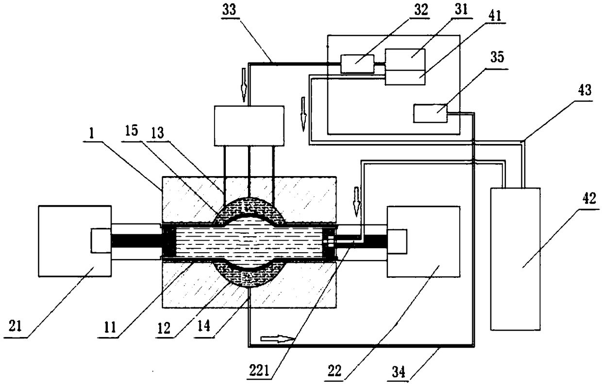
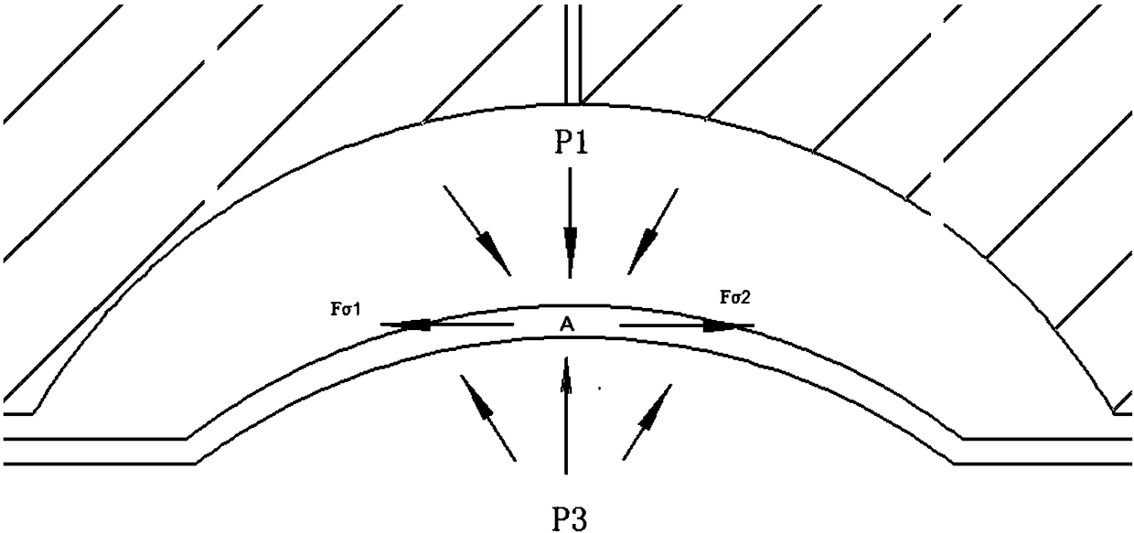
[0031] Such as Figure 1-2 as shown, figure 1 It is a structural schematic diagram of a pipe fitting internal high pressure external low pressure forming machine proposed by the present invention, figure 2 It is a schematic diagram of a pipe fitting internal high pressure external low pressure forming method proposed by the present invention and the force analysis under the working state of the forming machine.

[0032] refer to figure 1 , a kind of pipe fitting internal high pressure external low pressure forming method proposed by the present invention comprises the following steps:

[0033] S1. Put the pipe fitting to be formed into the mold cavity, an expanding area 15 is formed between the pipe fitting to be formed and the inner wall of the cavity, and the mold is provided with a first through hole 13 and a second through hole 14, through which the first through hole 13 Continuously inject low-pressure fluid into the expansion area 15, and the low-pressure fluid is di...


PUM


Abstract

The invention discloses a method for forming a pipe fitting with internal high pressure and external low pressure. The method comprises the steps that a pipe fitting to be formed is put into a cavity,a swelling region is formed between the pipe fitting to be formed and the inner wall of the cavity, low pressure fluid is continuously injected into the swelling region, then high pressure fluid is injected into the inner part of the pipe fitting to be formed, the high pressure fluid forms the pressure on the outer wall of the pipe fitting to be formed, so that the pipe fitting to be formed expands to the swelling region, when the pipe fitting expands to fit the inner wall of the cavity, supplying of the low pressure fluid is stopped, the formed pie fitting is taken out, and a working cycle is completed. The invention further discloses a forming machine, and the pipe fitting is formed according to the forming machine for a pipe fitting with internal high pressure and external low pressure. According to the method for forming a pipe fitting with internal high pressure and external low pressure, a first through hole and a second through hole are formed in a die for circulating the low pressure fluid into and out of the swelling region, a certain pressure P1 is formed for pipe fitting, so that it is guaranteed that the pipe fitting can swell uniformly everywhere, and a good forming effect is achieved.

Description

technical field [0001] The invention relates to the technical field of pipe fitting production equipment, in particular to a pipe fitting internal high pressure external low pressure forming method and a forming machine. Background technique [0002] The production and processing of hot-end pipe fittings (connecting pipe fittings between the automobile engine and exhaust pipe) and body structural parts (automobile chassis supports, transverse and longitudinal beams, instrument beams, etc.) are mostly produced by internal high-pressure forming technology, that is, injection High-pressure water, the left and right side cylinders are fed to make the product expand to the required shape; the cross-sectional area of ​​the hot-end pipe fittings generally changes greatly, that is, the local expansion is large, and the expansion area is prone to cracking; the conventional process is to carry out Multiple annealing and multiple forming can meet the forming requirements. The specific ...

Claims


Application Information

Patent Timeline
Patent Type & Authority Applications(China)
IPC IPC(8): B21D26/033B21D26/047B21D26/041
CPCB21D26/033B21D26/041B21D26/047
Inventor 郑俞陈旭琳郑玉磊陈绍明邓小波杨杰徐炎
Owner BAOLONG ANHUI AUTO PARTS
Why Eureka
Try Eureka