Positioning device for machining cam shaft and cam by milling machine

A positioning device, milling machine processing technology, applied in the direction of positioning device, metal processing equipment, metal processing machinery parts, etc., can solve the problems of unfavorable use, inconvenient fixing, time delay, etc., and achieve the effect of saving time, easy operation and convenient use

Inactive Publication Date:
View PDF8 Cites 3 Cited by
  • Summary
  • Abstract
  • Description
  • Claims
  • Application Information

AI Technical Summary

Problems solved by technology

[0003] The patent application number is 201720031798.5. The invention patent discloses a special milling machine for brake camshafts. It includes a machine tool body, a fixture and a tool that are located opposite to the machine tool body. device, the positioning device includes a support arm perpendicular to the side wall, and a piston pushing device on the support arm. The piston rod of the piston pushing device is connected with a conflicting component, and the conflicting component includes a Positioning rod, the measuring stud positioned at one end of the positioning rod, but the positioning device used by the existing milling machine to process the camshaft cam is relatively troublesome when performing positioning work, and it is not easy to fix, delays time, and is not conducive to people's use. With the advancement of technology and the development of society, people have put forward higher requirements for the positioning device of milling machines. Therefore, we have proposed a positioning device for milling machines to process camshafts and cams to solve the above problems.

Method used


Image

  • Positioning device for machining cam shaft and cam by milling machine
  • Positioning device for machining cam shaft and cam by milling machine
  • Positioning device for machining cam shaft and cam by milling machine

Examples


Embodiment Construction

[0024] The following will clearly and completely describe the technical solutions in the embodiments of the present invention in conjunction with the accompanying drawings in the embodiments of the present invention. Obviously, the described embodiments are only some of the embodiments of the present invention, not all of them.

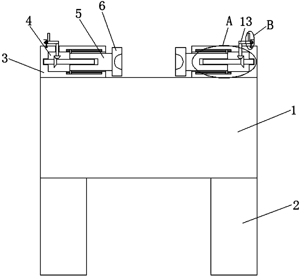
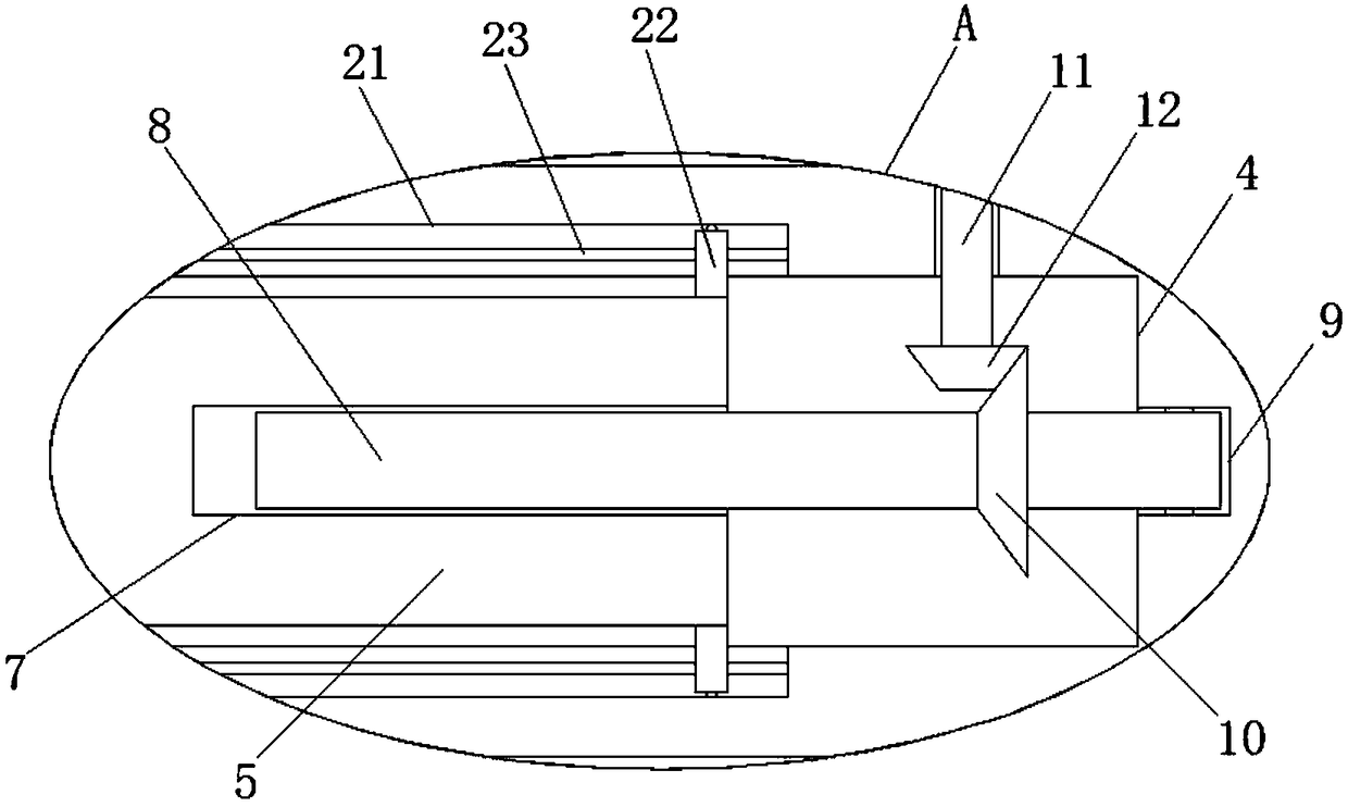
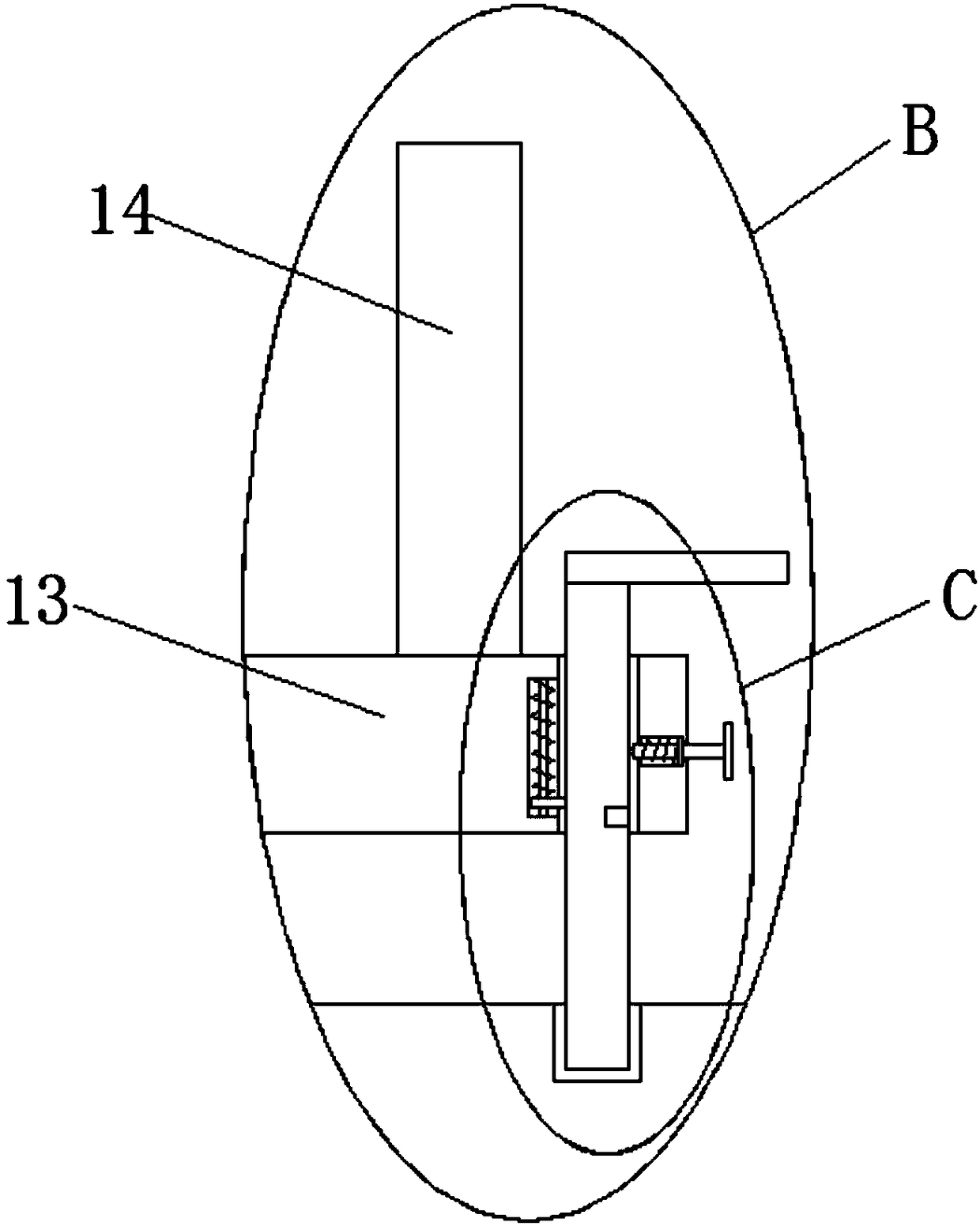
[0025] refer to Figure 1-5 , a positioning device for machining camshaft cams with a milling machine, comprising a fixed table 1, two fixed columns 2 are welded on the bottom of the fixed table 1, and two positioning device bodies 3 are symmetrically arranged on the top of the fixed table 1, and the two positioning devices The sides of the body 3 that are close to each other are provided with grooves 4, and a positioning rod 5 is slidably installed in the groove 4, and one end of the positioning rod 5 extends to the outside of the groove 4, and the ends of the two positioning rods 5 that are close to each other are welded. Positioning block 6, one en...


PUM


Abstract

The invention discloses a positioning device for machining a cam shaft and a cam by a milling machine. The positioning device comprises a fixing table, two fixing columns are welded at the bottom of the fixing table, two positioning device bodies are symmetrically arranged at the top of the fixing table, grooves are formed in the sides, close to each other, of the two positioning device bodies, positioning rods are installed in the grooves in a sliding mode, one ends of the positioning rods extend out of the grooves, and positioning clamping blocks are welded to the ends, close to each other,of the two positioning rods; and first rotating shaft grooves are formed in the ends, located in the grooves, of the positioning rods, first rotating shafts are rotationally installed in the first rotating shaft grooves, one ends of the first rotating shafts extend out of the first rotating shaft grooves, second rotating shaft grooves are formed in the inner walls of the sides, far away from the positioning rods, of the grooves, and the second rotating shaft grooves are rotationally connected with the first rotating shafts. According to the positioning device, the structure is simple, the useis convenient, through the positioning device bodies, the positioning work can be more conveniently carried out, moreover, connecting rods can be easier to fix, the operation is easy, the time is saved, and the use by people can be facilitated to a greater degree.

Description

technical field [0001] The invention relates to the technical field of processing equipment, in particular to a positioning device for milling a camshaft cam with a milling machine. Background technique [0002] A milling machine is a machine tool that uses a milling cutter to mill a workpiece. In addition to milling planes, grooves, gear teeth, threads and spline shafts, a milling machine can also process more complex profiles, and its efficiency is higher than that of a planer. It is used in machinery manufacturing and Widely used in the repair sector. [0003] The patent application number is 201720031798.5. The invention patent discloses a special milling machine for brake camshafts. It includes a machine tool body, a fixture and a tool that are located opposite to the machine tool body. device, the positioning device includes a support arm perpendicular to the side wall, and a piston pushing device on the support arm. The piston rod of the piston pushing device is conn...

Claims


Application Information

Patent Timeline
Patent Type & Authority Applications(China)
IPC IPC(8): B23Q3/06
CPCB23Q3/062
Inventor 樊育东李作崙陈建明
Why Eureka
Try Eureka