
Combined fixture for grinding material flow processing for cross-section-variable special-shaped channels

An abrasive flow machining and combined fixture technology is applied in the direction of manufacturing tools, grinding workpiece supports, metal processing equipment, etc. It can solve problems such as inconvenience in precision machining, and achieve the effects of reasonable fixture design, improved processing efficiency, and improved utilization efficiency.

Active Publication Date: 2018-09-14
NANJING UNIV OF AERONAUTICS & ASTRONAUTICS
View PDF8 Cites 4 Cited by
  • Summary
  • Abstract
  • Description
  • Claims
  • Application Information

AI Technical Summary

Problems solved by technology

[0004] The purpose of the present invention is to design a set of reasonable, convenient and available abrasive flow processing combination fixtures for variable cross-section special-shaped channels in the existing various types of automobile engines, so as to realize the smooth flow of the inner hole of the workpiece. Protect the flow channel from being damaged during the finishing process

Method used


Image

  • Combined fixture for grinding material flow processing for cross-section-variable special-shaped channels
  • Combined fixture for grinding material flow processing for cross-section-variable special-shaped channels
  • Combined fixture for grinding material flow processing for cross-section-variable special-shaped channels

Examples


Embodiment Construction

[0026] The present invention will be further described below in conjunction with the accompanying drawings and embodiments.

[0027] like Figure 1-7 shown.

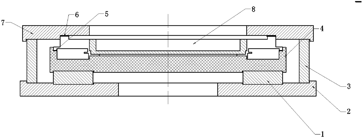
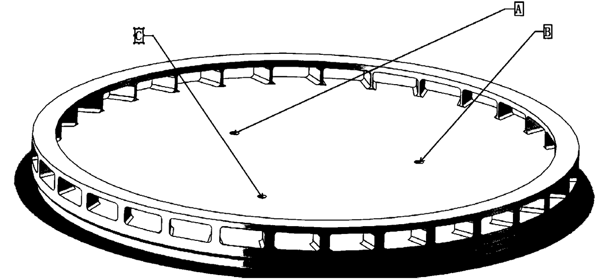
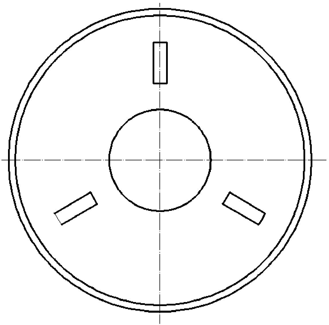
[0028] A combination fixture for abrasive flow machining with variable cross-section and special-shaped channels, the assembly diagram is as follows figure 1 As shown, the whole set of fixtures consists of two sets of inner and outer fixtures, wherein the outer fixture includes: fixed support block 1, outer fixture base 2, upper cover support ring 3, workpiece base 4, base gasket 5, upper cover plate 6, and upper cover of the fixture 7 and the outer fixture base 2, the outer fixture base 2 is fixed on the workbench of the abrasive flow processing machine tool, the workpiece base 4 is installed on the outer fixture base 2 through the fixed support block 1 so that the abrasive material is formed between the outer fixture base 2 and the workpiece base 4 channel, the workpiece is fixed on the workpiece base 4 through the l...


PUM


Abstract

A combined fixture for grinding material flow processing for cross-section-variable special-shaped channels is characterized in that the combined fixture comprises a workpiece exterior fixture and aninner-hole guide mandrel; the workpiece exterior fixture comprises a fixing and supporting block (1), an outer fixture base (2), an upper cover support ring (3), a workpiece base (4), a base gasket (5), an upper cover plate (6) and an upper fixture cover (7); the outer fixture base (2) is fixed to a workbench of a grinding material flow processing machine tool; the workpiece base (4) is mounted onthe outer fixture base (2) through the fixing and supporting block (1) to enable a grinding material channel to be formed between the outer fixture base (2) and the workpiece base (4); a workpiece isfixed to the workpiece base (4) through a limiting groove; the upper cover support ring (3) is mounted between the outer fixture base (2) and the upper fixture cover (7); the inner-hole guide mandrel(8) is located at the center of the workpiece and fixed to the workpiece base (4). The combined fixture has the advantages that the reasonable fixture is provided for reducing surface roughness of the special-shaped channels by grinding material flows, and has a reasonable design, a simple structure and an obvious effect.

Description

technical field [0001] The invention relates to a processing jig, in particular to a special jig for abrasive flow processing equipment, in particular to a combined jig for precise finishing machining of variable cross-section and special-shaped channel surfaces of complex workpieces. Background technique [0002] As we all know, a large number of parts in various types of automobile engines contain many complex variable-section special-shaped channels. With the increasing requirements for aerodynamic performance, the surface roughness requirements for special-shaped channels are also getting higher and higher. Abrasive flow machining technology is the latest fine grinding and finishing technology. Under the action of pressure, the abrasive flows through the surface of the workpiece to be processed, thereby reducing the roughness of the workpiece surface. [0003] In the process of using abrasive flow processing for variable cross-section special-shaped channels, due to the ...

Claims


Application Information

Patent Timeline
IPC IPC(8): B24B31/116B24B41/06
CPCB24B31/116B24B41/06
Inventor 孙玉利赵路刘志刚赵建社卢文壮左敦稳施凯博
Owner NANJING UNIV OF AERONAUTICS & ASTRONAUTICS
Learn More