
Production equipment and technology for furniture based on polypropylene composite material

A composite material and production equipment technology, applied in the field of furniture blow molding, can solve problems such as low utilization rate of raw materials, and achieve the effect of solving low utilization rate, ensuring work stability and reliability, and stable production

Inactive Publication Date: 2018-09-14
长兴水木机电有限公司
View PDF0 Cites 1 Cited by
  • Summary
  • Abstract
  • Description
  • Claims
  • Application Information

AI Technical Summary

Problems solved by technology

[0003] The purpose of the present invention is to address the deficiencies of the prior art, and provide furniture production equipment and production technology based on polypropylene composite materials. While clamping and fixing the blank through the clamping assembly, the cutting knife is inserted into the blank mold and inside, and the While the holding component drives the transfer of the blank mold, it drives the cutter to cut the blank mold neatly; solves the technical problem of low utilization rate of raw materials in the prior art

Method used


Image

  • Production equipment and technology for furniture based on polypropylene composite material
  • Production equipment and technology for furniture based on polypropylene composite material
  • Production equipment and technology for furniture based on polypropylene composite material

Examples


Embodiment 1

[0040] Embodiments of the present invention are described in detail below, examples of which are shown in the drawings, wherein the same or similar reference numerals designate the same or similar elements or elements having the same or similar functions throughout. The embodiments described below by referring to the figures are exemplary and are intended to explain the present invention and should not be construed as limiting the present invention.

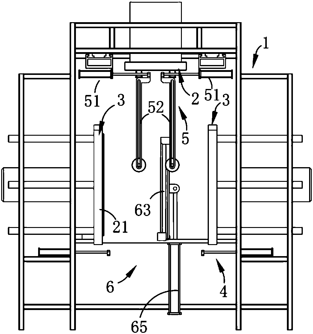
[0041] Such as figure 1 , 2 , 3 and 4, based on polypropylene composite material furniture production equipment, including a frame 1, a blow molding port 2 installed on the frame 1, a forming mold 3 and a sealing mechanism 4, it is characterized in that it also includes:

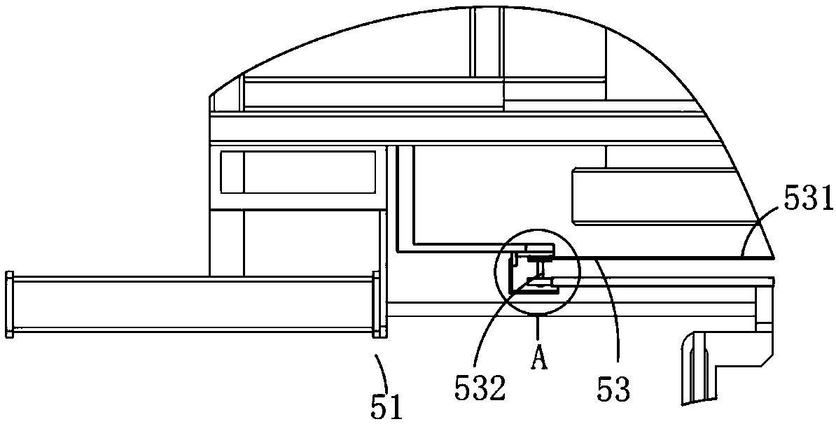
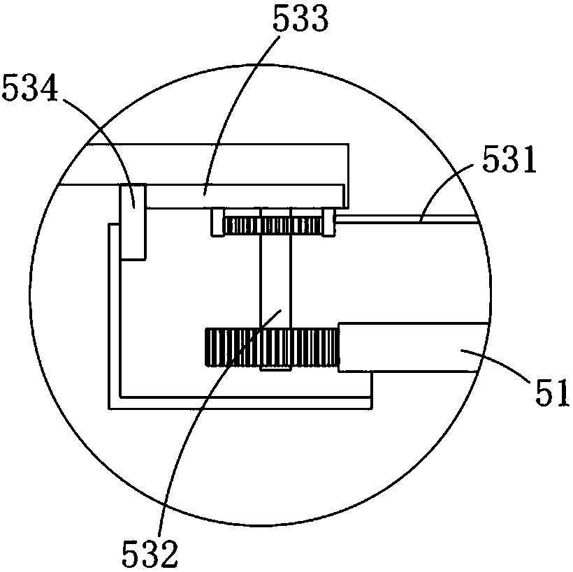
[0042]The transfer mechanism 5, the transfer mechanism 5 is located between the blow molding port 2 and the molding mold 3, which includes a clamping assembly 51 symmetrically arranged on the frame 1 and located on both sides of the molding mold 3, installed o...

Embodiment 2

[0049] Such as figure 1 and 5 As shown, the parts that are the same as or corresponding to those in Embodiment 1 adopt the reference numerals corresponding to Embodiment 1. For the sake of simplicity, only the differences between Embodiment 1 and Embodiment 1 are described below; the differences between Embodiment 2 and Embodiment 1 The advantage is that the clamping assembly 51 is arranged in a symmetrical structure, which includes a sliding table 511 slidably arranged on the frame 1, a splint 512 arranged on the sliding table 511, and a clamping plate 512 fixedly arranged on the sliding table 511. The driving part 513 that drives the clamping plate 512 to reciprocate, the demoulding assembly 52 is arranged at both ends of the clamping plate 512 and is located outside the forming mold 3; in this embodiment, the driving part 513 is preferably The cylinder, wherein the two ends of the demoulding assembly 42 are fixedly arranged on the two ends of the splint 413 .

[0050] Fur...

Embodiment 3

[0052] Such as figure 1 , 7 and 9, wherein the same or corresponding parts as in the second embodiment adopt the corresponding reference numerals of the second embodiment, for the sake of simplicity, only the difference between the second embodiment and the second embodiment is described below; the third embodiment and the second embodiment The difference is that the edge material cutting mechanism 6 includes a receiving portion 61 arranged under the forming mold 3, a workbench 62 at the end of the accepting portion 61, and a reversing disc 63 arranged on the workbench 62. , a limit bar 64 fixedly arranged on the workbench 62 and in contact with the reversing disc 63 , and a transmission part 65 that drives the reversing disc 63 to move along the limit bar 64 to realize the horizontal placement of the reversing disc 63 .

[0053] Among them, such as Figure 7 , 8 As shown in and 9, the reversing disc 63 is provided with a disc structure, which includes a positioning groove ...


PUM


Abstract

The invention relates to the technical field of furniture blow molding production, in particular to production equipment and technology for furniture based on a polypropylene composite material. The production equipment comprises a rack, a blow molding port, a molding die, a sealing mechanism, a transferring mechanism and a leftover material cutting mechanism; the transferring mechanism comprisesa clamping assembly, a demolding assembly and a shearing assembly, and the shearing assembly is in interrupted transmission connection with the clamping assembly; the shearing assembly comprises a cutter and a transmission part, the clamping assembly drives the cutter to insert the cutter into the upper end of a blank die while clamping and fixing the blank die, and the cutter moves reversely to flatly separate a raw material from the blank die; the blank die transferred by the clamping assembly is horizontally placed and treated through the leftover material cutting mechanism to be subject tomanual leftover material cutting, and a blank is clamped and fixed through the clamping assembly while the clamping assembly drives the cutter to insert the cutter into the blank die, and the clamping assembly drives the blank die to be transferred and drives the cutter to orderly cut the blank die at the same time. The technical problem that in the prior art, the raw material using rate is low is solved.

Description

technical field [0001] The invention relates to the technical field of furniture blow molding production, in particular to furniture production equipment and a production process based on polypropylene composite materials. Background technique [0002] With the improvement of people's living standards, outdoor activities have increased, and more and more household furniture products are made of plastic products; at this stage, outdoor furniture products are mostly produced by blow molding; however, at this stage, the blow molding production of plastic tabletops is mostly The manual operation method realizes demoulding, transfer and edge material cutting; for the blow molding production of some large desktops, the manual demoulding is easy to cause damage to the desktop, and at the same time, the labor load of the workers is large, and the production efficiency is low; in addition, in the traditional In the blow molding production process, after the blank mold is blow-molded,...

Claims


Application Information

Patent Timeline
Patent Type & Authority Applications(China)
IPC IPC(8): B29C49/04B29C49/42B29C47/08B29C33/44
CPCB29C49/04B29C33/44B29C48/25B29C49/4252
Inventor 王泽凡王优杰王泽莉
Owner 长兴水木机电有限公司
Learn More