
Deformation detection device

A detection device and deformation technology, applied in electromagnetic measurement devices, electric/magnetic solid deformation measurement, signal transmission systems, etc., can solve the problems of unfavorable data downlink, high transmission bandwidth, easy to be affected by weather, etc., and achieve environmental adaptability Strong, reduce the effect of the use of cables

Pending Publication Date: 2018-09-14
DONGGUAN FRONTIER TECH INST
View PDF0 Cites 5 Cited by
  • Summary
  • Abstract
  • Description
  • Claims
  • Application Information

AI Technical Summary

Problems solved by technology

First of all, this method of using a digital camera to take pictures to obtain deformation data cannot obtain the deformation of the top of the capsule, which will result in the loss of part of the deformation data, making the obtained deformation results inaccurate
Secondly, the image data obtained by taking photos generally requires a large storage space and high transmission bandwidth, which is not conducive to data downloading; in addition, digital cameras are greatly affected by external environmental factors, and cannot take clear pictures at night. In rainy, snowy or foggy weather conditions, the camera lens will be interfered to a certain extent and cannot work well
[0004] Aiming at the problems of using digital cameras to take pictures to obtain deformation data in related technologies, such as data loss, vulnerability to weather, and high requirements for image data storage and transmission, no effective solutions have been proposed so far.

Method used


Image

  • Deformation detection device

Examples


Embodiment Construction

[0020] The following will clearly and completely describe the technical solutions in the embodiments of the present invention with reference to the accompanying drawings in the embodiments of the present invention. Obviously, the described embodiments are only some, not all, embodiments of the present invention. All other embodiments obtained by persons of ordinary skill in the art based on the embodiments of the present invention belong to the protection scope of the present invention.

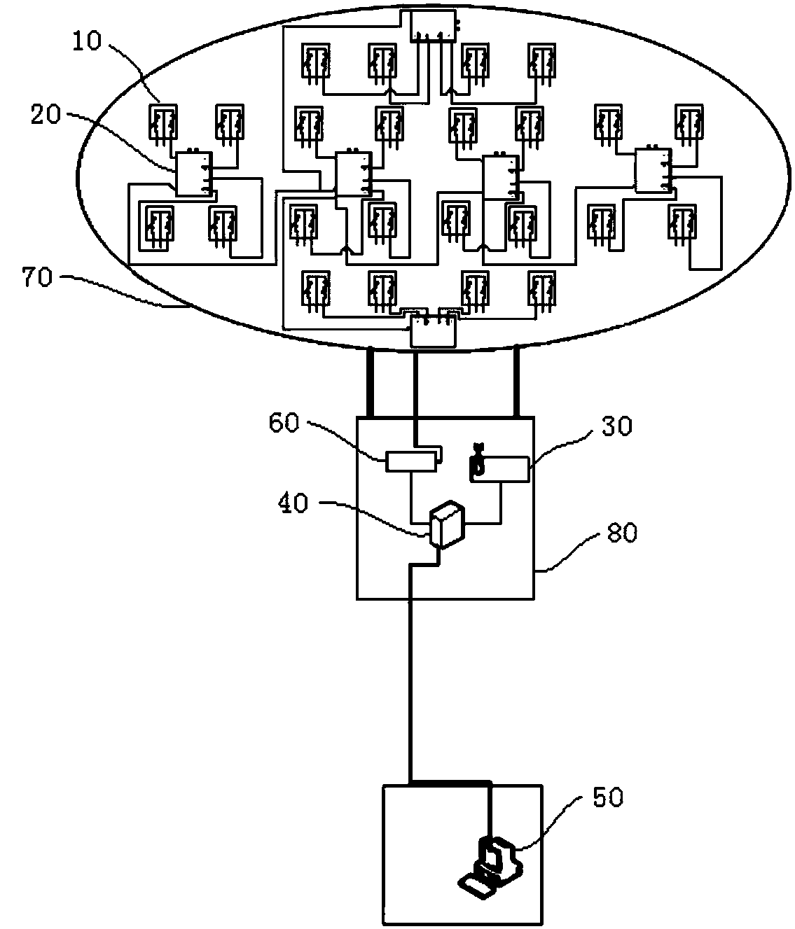
[0021] Such as figure 1 As shown, the deformation detection device according to the embodiment of the present invention is used for the deformation detection of the airship capsule, and the deformation detection device includes:

[0022] A plurality of strain sensors 10 are attached to the surface of the capsule 70 for generating stress and strain data according to the deformation of the surface of the capsule 70;

[0023] At least one collection and transmission module 20, a plurality of st...


PUM


Abstract

The invention discloses a deformation detection device which is used for deformation detection of an airship capsule. The deformation detection device comprises multiple strain sensors which are attached to the surface of the capsule and used for generating the stress strain data according to the deformation of the surface of the capsule; at least one acquisition and transmitting module which is correspondingly connected with multiple strain sensors to acquire the stress strain data; a wireless receiving module which is wirelessly connected with the acquisition and transmitting module; and a ground monitoring center which is connected with the wireless receiving module, wherein the acquisition and transmitting module transmits the acquired stress train data to the ground monitoring centerthrough the wireless receiving module so as to analyze the stress strain data and detect the deformation of the capsule. The strain sensors generate the stress strain data according to the deformationof the capsule, and wireless transmission of the stress strain data can be realized through the wirelessly connected acquisition and transmitting module and the wireless receiving module so that thedeformation of the capsule can be detected in real time, the environmental adaptability is high and effective deformation detection can be performed under various environmental conditions.

Description

technical field [0001] The invention relates to a deformation detection device, in particular to a deformation detection device used for deformation detection of a capsule. Background technique [0002] When airships are in the air, due to factors such as temperature difference between day and night, the shape of the airship capsule will change continuously. Therefore, obtaining the deformation and deformation rules of the capsule is the basis for the development of flexible inflatable structures. Due to the particularity of the flexible material of the capsule, many detection methods cannot be used, and since the airship stays in the sky, the difficulty of detection is further increased. [0003] The existing deformation detection method is to arrange a plurality of marking points on the capsule, use multiple digital cameras to take pictures for image acquisition, and perform image processing on the collected image data to obtain the deformation result of the capsule. Firs...

Claims


Application Information

Patent Timeline
IPC IPC(8): G01B7/16G08C17/02G08C23/06
CPCG08C17/02G08C23/06G01B7/18
Inventor 不公告发明人
Owner DONGGUAN FRONTIER TECH INST
Learn More