
Complete fiber-optic vector microphone probe

A microphone and vector technology, used in the measurement of ultrasonic/sonic/infrasonic waves, instruments, measuring devices, etc., can solve the problems of complex silicon micro-process flow, high phase matching requirements, and high background noise, and achieve easy formation of arrays, anti-electromagnetic Effects of strong interference ability, multiple selectivity and possibility

Pending Publication Date: 2019-05-31
QUFU NORMAL UNIV
View PDF0 Cites 2 Cited by
  • Summary
  • Abstract
  • Description
  • Claims
  • Application Information

AI Technical Summary

Problems solved by technology

On the other hand, the measurement of the vector particle velocity U is calculated based on the sound pressure gradient of two sound pressure microphones with phase matching, such as the sound intensity meter, so as an indirect method to obtain the particle velocity, the performance There are technical limitations, especially high requirements for phase matching and narrow operating frequency band; the other is a particle velocity sensor based on silicon microstructure, which is also a microphone that directly measures the velocity of air acoustic particles. Please refer to my previous invention patent : A sensor for measuring the vibration velocity of air acoustic particles and its manufacturing method, and adopts a silicon micro-process structure, a structural form of a heat source wire-sensitive wire, and the resistance difference generated by the thermal resistance effect is demodulated by the resistance difference Therefore, the main defect of the microphone is that the sensitivity is low and the noise floor is high due to the resistive type. After the circuit signal is amplified, although the sensitivity can be increased to a certain extent, the noise floor will also increase accordingly. Therefore, the signal-to-noise ratio is not high; and because of the extremely large aspect ratio of the heat source wire and the sensitive wire, its molding is difficult and the silicon micro-process is complicated; in addition, its cost is high, such as platinum material costs and various process equipment Processing fee, etc.

Method used


Image

  • Complete fiber-optic vector microphone probe
  • Complete fiber-optic vector microphone probe
  • Complete fiber-optic vector microphone probe

Examples


no. 1 example 1

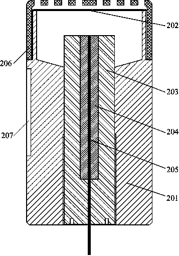
[0051] In the first embodiment of the present invention, a complete optical fiber vector microphone probe adopts a schematic cross-sectional view of a fiber optic scalar microphone probe structure that directly measures the acoustic signal scalar sound pressure P, as shown in FIG. figure 2 As shown, it includes: a structure 201, a diaphragm 202, a ferrule sleeve 203, a ferrule 204, a single-mode optical fiber 205, a mesh cover 206 and a groove 207 (the groove on the proximal surface is not shown). The optical fiber scalar microphone probe is based on the Fabry-Perot interferometer structure, and its specific composition is described as follows: the structure body 201 is a hollow structure, the uppermost cylindrical cavity structure is used to fix the diaphragm 202, and the lower part has A section of internal thread is used to fix ferrule sleeve 203 with corresponding external thread. The ferrule sleeve 203 is used to fix the ferrule 204 , and has ventilation slots for static...

no. 2 example

[0055] The second embodiment of the present invention is a preferred embodiment. Based on the structural characteristics of a complete optical fiber vector microphone probe of the present invention, the two-dimensional optical fiber vector microphone probe and the one-dimensional optical fiber vector microphone probe can also be designed and determined first, Then, based on the structural dimensions of the above two microphone probes, the dimensions of the corresponding grooves on the two adjacent surfaces are given to determine the design of the optical fiber scalar microphone probe, and finally the bonding assembly between all probes is completed according to the instructions.

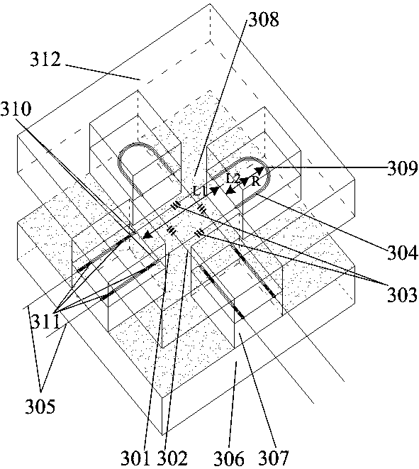
[0056] The second embodiment of the present invention is a two-dimensional optical fiber vector microphone probe with orthogonal directivity of "8" directivity used by a complete fiber optic vector microphone probe to directly measure the particle velocity U of the acoustic signal vector. Cascaded mic...


PUM


Abstract

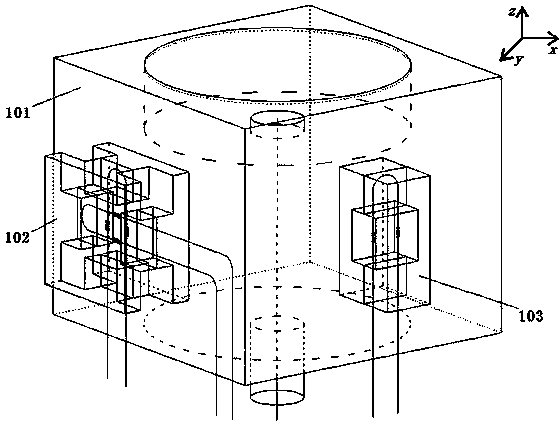
The invention discloses a complete fiber-optic vector microphone probe. The complete fiber-optic vector microphone probe comprises an optical fiber scalar microphone used for directly measuring the scalar acoustic pressure P of an acoustic signal, a two-dimensional optical fiber vector microphone used for directly measuring two-dimensional orthogonal components of the vector particle vibration speed U of the acoustic signal and a one-dimensional optical fiber vector microphone used for directly measuring the vector particle vibration speed U of the acoustic signal. The outer surface of the periphery of an optical fiber scalar microphone structural body is in a cuboid shape, two adjacent vertical planes of the optical fiber scalar microphone structural body respectively bear the two-dimensional optical fiber vector microphone and the one-dimensional optical fiber vector microphone, each surface of the optical fiber scalar microphone structural body is provided with a groove having the same size as the outer structure of the corresponding two-dimensional optical fiber vector microphone or the one-dimensional optical fiber vector microphone to allow the two-dimensional optical fiber vector microphone or the one-dimensional optical fiber vector microphone to be strictly pasted and inlaid in the two grooves, and the orientations and the positions of the two grooves must ensure thatthe three-dimensional 8-shaped directivity formed by the two-dimensional optical fiber vector microphone and the one-dimensional optical fiber vector microphone meets a Cartesian three-dimensional rectangular coordinate system.

Description

technical field [0001] The invention discloses a complete optical fiber vector microphone probe, particularly relates to the use of an all optical fiber structure for synchronous co-point measurement of sound pressure P and a complete acoustic signal composed of three-dimensional components Ux, Uy, and Uz of particle velocity U, which has anti-electromagnetic Strong interference ability, high sensitivity, high signal-to-noise ratio, easy to form an array, especially comprehensive acoustic performance characteristics of three-dimensional orthogonal "8" directivity, and simple structure, small size, light weight, low cost, and easy to implement. Background technique [0002] With the rapid development of optical fiber sensing technology, its application range is becoming wider and wider. Compared with various traditional electric microphones, fiber optic microphones have unique advantages of fiber optics, such as anti-electromagnetic interference, high sensitivity, high signal...

Claims


Application Information

Patent Timeline
IPC IPC(8): G01H9/00
Inventor 赵龙江程进齐文海
Owner QUFU NORMAL UNIV
Learn More