Lane change estimation device, lane change estimation method, and storage medium
A lane and estimation technology, applied in the field of lane change estimation devices
- Summary
- Abstract
- Description
- Claims
- Application Information
AI Technical Summary
Problems solved by technology
Method used
Image
Examples
Deformed example 1
[0102] In Modification 1, the second index value derivation map 154 used for deriving the second index value is switched to the conditional second index value derivation map 155 according to the lighting state of the direction indicator of the third vehicle m3.
[0103] Figure 9 It is a flowchart showing the flow of processing executed by the first control unit 120 of the modified example. The processing of steps S200~S216 and Figure 5 The processing of steps S100 to S116 is the same, and therefore description thereof will be omitted.
[0104] After the process of step S216, the first control unit 120 determines whether the direction indicator of the third vehicle m3 is lit to indicate the intention to change lanes to the first lane L1 based on the recognition result of the outside world recognition unit 121 (step S218).
[0105] When the direction indicator of the third vehicle m3 lights up to indicate the intention to change lanes to the first lane L1, the estimation u...
Deformed example 2
[0110] The estimation unit 126 may further add the travel history of the third vehicle m3 to estimate the possibility of the third vehicle m3 changing lanes from the second lane L2 to the first lane L1. Figure 11 It is a figure which shows an example of the travel history of the 3rd vehicle m3. right with Figure 4 The description of the same content is omitted. In the illustrated example, the third vehicle m3 accelerates and travels (passes) so as to exist in front of the own vehicle M from behind the own vehicle M. When the third vehicle m3 is accelerating and the third vehicle m3 overtakes the host vehicle M, the estimation unit 126 compares the third vehicle m3 to the lane when the third vehicle m3 does not accelerate but the third vehicle m3 overtakes the host vehicle M. The possibility of change is estimated to be high.
[0111] As described above, when the third vehicle m3 overtakes the own vehicle M, when the third vehicle m3 passes the own vehicle M as indicated b...
Deformed example 3
[0114] When there is a merging road (or when the lane adjacent to the lane on which the own vehicle M travels disappears), the virtual vehicle setting unit 123A sets a virtual second vehicle vm2 corresponding to the second vehicle m2. The first index value derivation unit 124 regards the virtual second vehicle vm2 as the second vehicle m2 to derive the first index value.
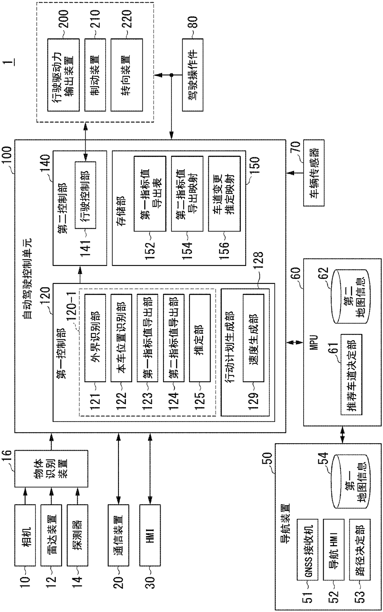
[0115] A vehicle system 1A according to Modification 2 includes an automatic driving control unit 100A instead of the automatic driving control unit 100 . Figure 12 It is a diagram showing the functional configuration of an automatic driving control unit 100A according to Modification 2. The automatic driving control unit 100A includes, for example, a first control unit 120A. The first control unit 120A includes a virtual vehicle setting unit 123A in addition to the functional configuration of the first control unit 120 .
[0116] Figure 13 It is a figure which shows an example of the scene where a merg...
PUM
 Abstract
Description
Claims
Application Information
 - R&D
- Intellectual Property
- Life Sciences
- Materials
- Tech Scout
- Unparalleled Data Quality
- Higher Quality Content
- 60% Fewer Hallucinations
Browse by: Latest US Patents, China's latest patents, Technical Efficacy Thesaurus, Application Domain, Technology Topic, Popular Technical Reports.
© 2025 PatSnap. All rights reserved.Legal|Privacy policy|Modern Slavery Act Transparency Statement|Sitemap|About US| Contact US: help@patsnap.com


