Underground water storage treatment device for sponge city construction

A technology for building land and sponge cities, applied in water supply installations, water/sewage treatment, water/sludge/sewage treatment, etc., can solve the problem of reducing the liquid capacity of reservoirs, the inconvenience of water resource reuse, rainwater precipitation and Filtering and other issues to achieve the effect of improving timeliness and efficiency, saving resources for sponge city construction, and improving utilization

Inactive Publication Date: 2018-08-14
HUNAN UNIV OF ARTS & SCI
View PDF8 Cites 2 Cited by
  • Summary
  • Abstract
  • Description
  • Claims
  • Application Information

AI Technical Summary

Problems solved by technology

[0006] Aiming at the deficiencies of the prior art, the present invention provides an underground water storage treatment device for sponge city construction, capable of effectively precipitating and filtering the liquid stored in the underground storage tank, and can timely and effectively remove sediment and impurities and other garbage. It solves the problem of underground water storage in the process of sponge city construction. Due to the lack of timely precipitation and filtration of rainwater, the rainwater entrains solid waste and other sediments directly into the storage tank. Due to the sediment and The existence of impurities, while reducing the liquid capacity of the reservoir, also brings great inconvenience to the reuse of water resources

Method used


Image

  • Underground water storage treatment device for sponge city construction
  • Underground water storage treatment device for sponge city construction
  • Underground water storage treatment device for sponge city construction

Examples


Embodiment Construction

[0031] The following will clearly and completely describe the technical solutions in the embodiments of the present invention with reference to the accompanying drawings in the embodiments of the present invention. Obviously, the described embodiments are only some, not all, embodiments of the present invention. Based on the embodiments of the present invention, all other embodiments obtained by persons of ordinary skill in the art without making creative efforts belong to the protection scope of the present invention.

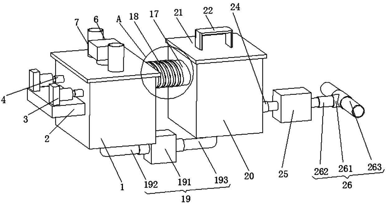
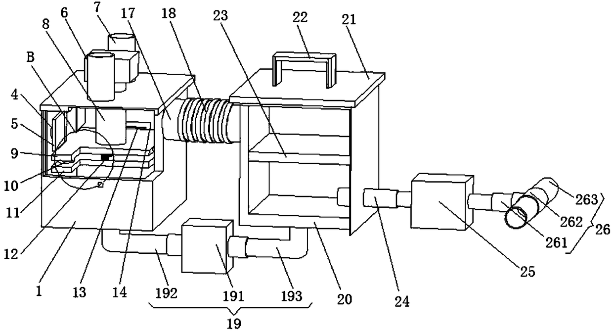
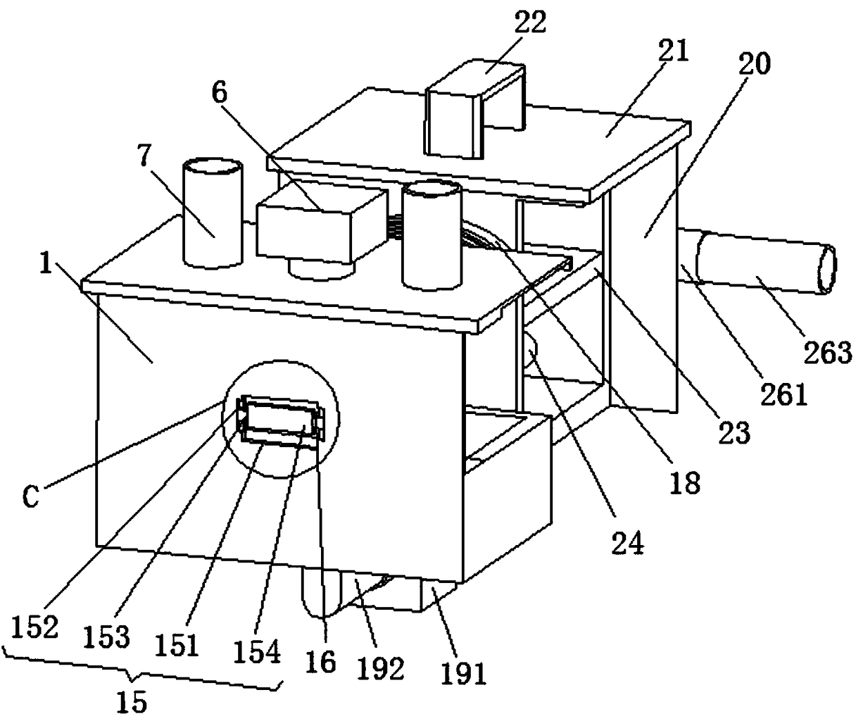
[0032] see Figure 1-6, an underground water storage treatment device for sponge city construction, comprising a processing container 1, a fixed bottom plate 2 is fixedly installed in the middle of the outer side of the processing container 1, and two hydraulic rods 3 are fixedly installed on the top of the fixed bottom plate 2, through The working hydraulic rod 3 drives the damping push rod 4 to push the movable plate 5, so that the movable plate 5 pushes the...


PUM


Abstract

The invention relates to the technical field of sponge city construction equipment, and discloses an underground water storage treatment device for sponge city construction. The underground water storage treatment device comprises a treatment accommodating apparatus. A fixing bottom plate is fixedly mounted in the middle of an outer side of the treatment accommodating apparatus, two hydraulic rodsare fixedly mounted on the top of the fixing bottom plate, the bottoms of shells of the two hydraulic rods are fixedly connected with the left side and the right side of the top of the fixing bottomplate, damping push rods are fixedly connected with pushing shafts of the two hydraulic rods, and the end, which is far away from the corresponding hydraulic rod, of each damping push rod is fixedly connected with the side, which is far away from the middle of the treatment accommodating apparatus, of a movable plate. The underground water storage treatment device for sponge city construction hasthe advantages that the hydraulic rods and the damping push rods are combined with one another, pushing work can be carried out on the movable plates, and accordingly precipitates on the tops of a precipitation plate can be efficiently cleaned; impurities, the precipitates and the like can be fed into an inner cavity of an underground water storage apparatus under the effect of an impurity leading-out through pipe, and accordingly the timeliness and the high efficiency of impurity cleaning work for the precipitates and the like can be effectively improved.

Description

technical field [0001] The invention relates to the technical field of sponge city construction equipment, in particular to an underground water storage treatment device for sponge city construction. Background technique [0002] Sponge city is a new generation of urban stormwater management concept. It refers to the city's good "elasticity" in adapting to environmental changes and responding to natural disasters caused by rainwater. It can also be called "water elastic city". [0003] The term commonly used in the world for sponge city is "low-impact development rainwater system construction". Take advantage of it. [0004] In the underground water storage work during the construction of the sponge city, due to the lack of timely precipitation and filtration of rainwater, the rainwater entrains solid waste and other sediments directly into the storage tank. Due to the existence of sediments and impurities, the storage capacity is reduced While reducing the liquid capacity...

Claims


Application Information

Patent Timeline
Patent Type & Authority Applications(China)
IPC IPC(8): E03F5/10E03F5/14
Inventor 杨品红毛亮石彭灵
Owner HUNAN UNIV OF ARTS & SCI
Why Eureka
Try Eureka