Battery cell encapsulation control method and device

A control method and technology of a control device, which are applied in the manufacture of secondary batteries, circuits, electrical components, etc., can solve the problems of easy generation of wrinkles, unevenness, and low efficiency of cell coating, and achieve the effect of improving quality.

Pending Publication Date: 2022-08-05
WUHAN YIFI LASER EQUIP CO LTD
View PDF1 Cites 0 Cited by
  • Summary
  • Abstract
  • Description
  • Claims
  • Application Information

AI Technical Summary

Problems solved by technology

[0005] Aiming at the technical problems in the prior art that the cell encapsulation efficiency is low, the degree of intelligence is not high, and it is easy to produce wrinkles or unevenness, the present invention provides a cell encapsulation control method

Method used


Image

  • Battery cell encapsulation control method and device
  • Battery cell encapsulation control method and device
  • Battery cell encapsulation control method and device

Examples


Embodiment 1

[0062] The present invention provides a control method and device for battery core wrapping, which has the advantages of high flatness, good quality, and good adaptability to different process requirements.

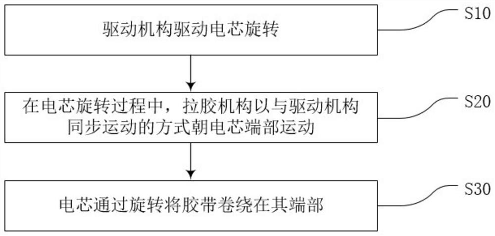
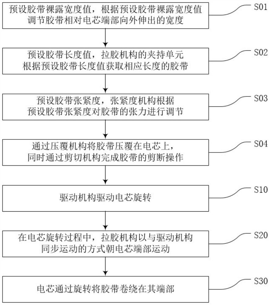
[0063] like figure 1 As shown in the figure, when the cell is covered with glue, the driving mechanism first drives the cell to rotate in step S10; then in step S20, during the rotation of the cell, the rubber-pulling mechanism moves toward the end of the cell in a synchronous motion with the driving mechanism, so that the The tape is continuously in a suitable tension state, and will not be too tight or too loose; finally, according to step S30, the battery cell is rotated to wind the tape around its end. Since the cell is in the process of encapsulating, the tape is continuously in a proper tension state, so that the flatness of the tape is better, that is, the quality of the encapsulation is higher. Wherein, the synchronous movement means that the horizontal speed of ...

Embodiment 2

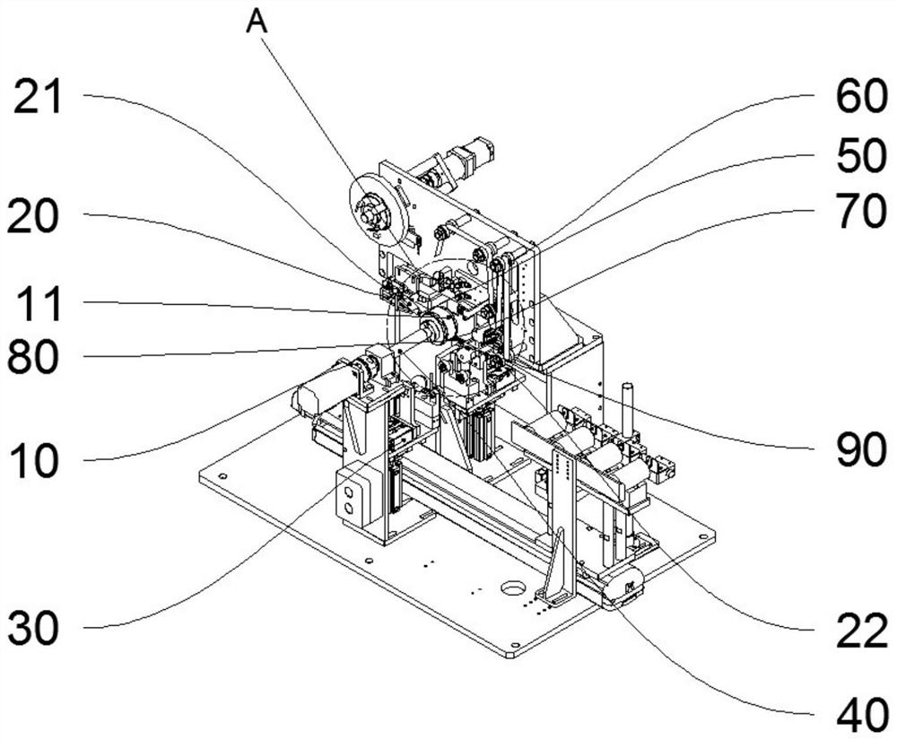
[0077] The present invention provides a control device for cell encapsulation, such as image 3 As shown, the control device for encapsulating the battery cell includes a driving mechanism 10, a rubber pulling mechanism 20 and a control unit 30. The control unit 30 obtains the rubber pulling according to the diameter of the battery cell and the linear speed of the battery core rotation. The synchronous proportional value between the driving unit of the mechanism and the driving unit of the driving mechanism, through the synchronous proportional value, the rubber pulling mechanism 10 is moved toward the end of the battery cell in a manner of synchronous movement with the driving mechanism.

[0078] Preferably, the rubber pulling mechanism and the driving unit of the driving mechanism are both high-precision servo motors. The control unit 30 is provided with a synchronous control device, and the synchronous control device is connected with two sets of high-precision servo motors...


PUM


Abstract

The invention relates to the technical field of batteries, in particular to a control method and device for battery cell encapsulation, and the control method for battery cell encapsulation comprises the following steps: a driving mechanism drives a battery cell to rotate, and an adhesive tape is wound on the end part of the battery cell through the rotation of the battery cell; and in the process that the battery cell rotates to wind the adhesive tape on the end part of the battery cell, the adhesive pulling mechanism moves towards the end part of the battery cell in a manner of synchronously moving with the driving mechanism. The operation of the rubber pulling mechanism and the driving mechanism is synchronously driven in the battery core rubber coating process, so that the rubber belt is continuously kept in a proper tensioning state in the rubber coating process, and the flatness of the rubber belt in the rubber coating process is improved.

Description

technical field [0001] The invention relates to the technical field of batteries, in particular to a control method and device for encapsulating a battery cell. Background technique [0002] With the progress and development of science and technology, intelligent manufacturing and automated production lines are more and more favored by enterprises. In the field of electric vehicles, the manufacturing of its core component, the power battery, is becoming more and more automated. In the production process of power batteries, there are many procedures, and due to their small size, the requirements for the integration and precision of the equipment are getting higher and higher. [0003] The patent document with the authorization number of CN215869519U discloses a gravity self-adaptive pole piece group glue and pressing device, including a glue guide bracket, a glue guide part and a glue part, wherein the glue guide bracket is vertically arranged; the glue guide The parts and ...

Claims


Application Information

Patent Timeline
Patent Type & Authority Applications(China)
IPC IPC(8): H01M10/04H01M10/0585
CPCH01M10/04H01M10/0585Y02P70/50
Inventor 冉昌林蔡汉钢庞久海
Owner WUHAN YIFI LASER EQUIP CO LTD
Why Eureka
Try Eureka