Laser radar device

A laser radar and laser emission technology, applied in the field of laser detection, can solve the problems of inability to adapt to the specific structure of the transmitting device and the receiving device, and the laser setting is not tight, and achieve the effect of adjustable position relationship, convenient assembly, and flexible space.

Pending Publication Date: 2018-09-14
HESAI TECH CO LTD
View PDF8 Cites 9 Cited by
  • Summary
  • Abstract
  • Description
  • Claims
  • Application Information

AI Technical Summary

Problems solved by technology

[0005] The technical problem to be solved by the present invention is that the distribution of the transmitting cabin and the receiving cabin of the laser radar device in the prior art cannot adapt to the specific structure of the transmitting device and the receiving device in the cabin, and the problem that the laser device is not tightly arranged in the prior art

Method used


Image

  • Laser radar device
  • Laser radar device
  • Laser radar device

Examples


Embodiment

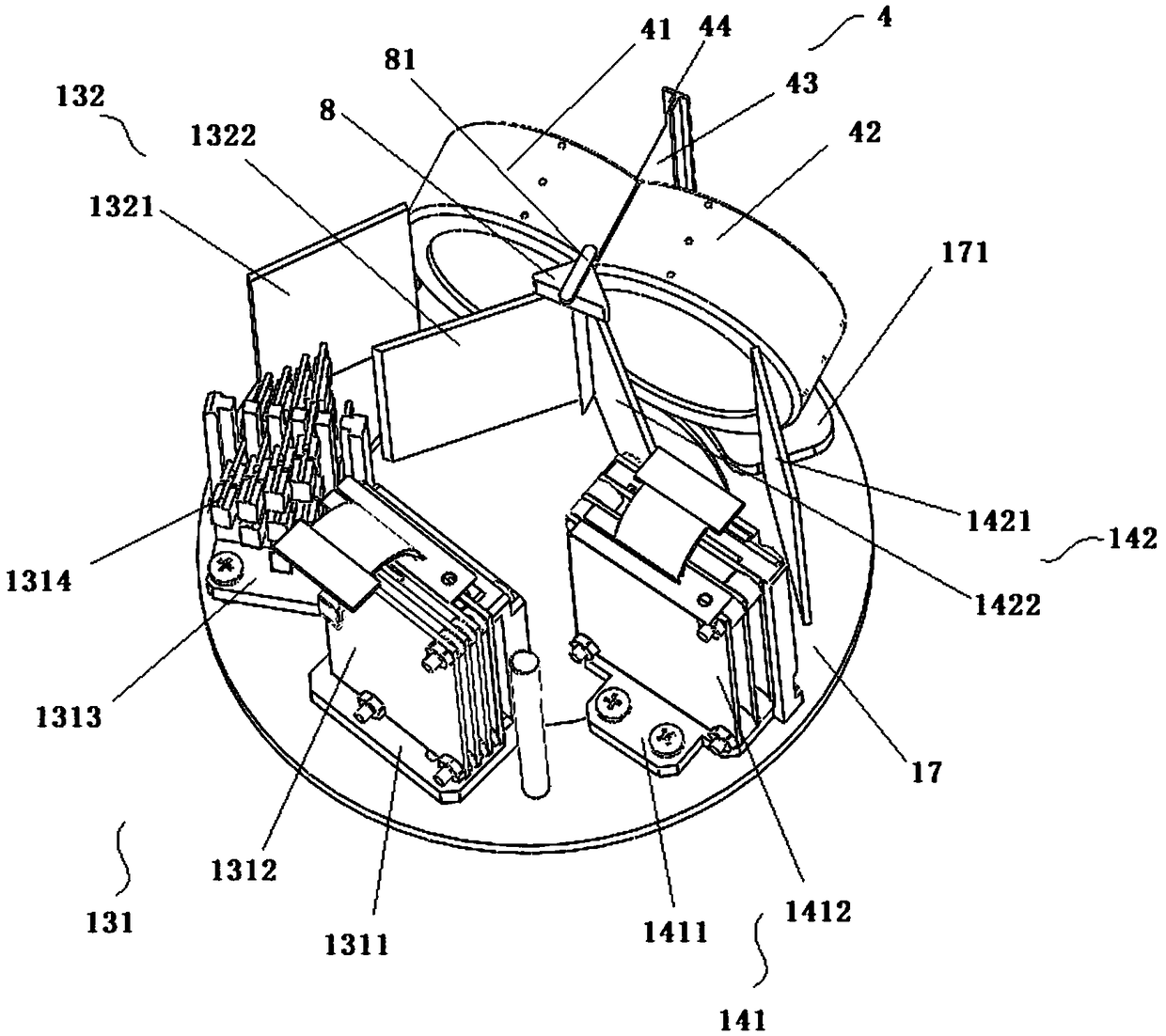
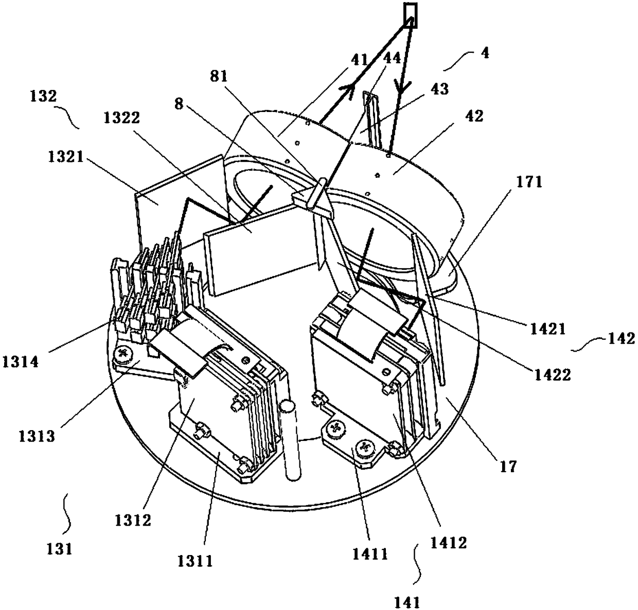
[0047] In order to solve the above technical problems, the present invention discloses a laser radar device, see Figure 1 to Figure 16 , the laser radar device includes a rotor 1, the rotor 1 includes an outer cylinder 11 and an inner cylinder 12, an optical lens assembly 4 is installed on the wall of the outer cylinder 11, and the two sides of the optical lens assembly 4 are distributed with A counterweight structure 5, the counterweight structure 5 includes a first counterweight structure and a second counterweight structure, both of the first counterweight structure and the second counterweight structure include a plurality of grooves 51, preferably, the The structures of the plurality of grooves 51 may be the same or different. As a preferred embodiment, in this embodiment, the plurality of grooves 51 forming the first counterweight structure are taken as an example: the first counterweight structure includes 12 grooves 51, specifically included in the outer cylinder 11 ...


PUM


Abstract

The invention relates to the technical field of laser detection and discloses a laser radar device. The device includes a rotor. The rotor is therein provided with an emitting cabin and a receiving cabin. An optical lens assembly is mounted on the side wall of the rotor. The optical lens includes an optical emitting lens and an optical receiving lens communicating with the emitting cabin and the receiving cabin respectively. The emitting cabin is therein provided with an emitting assembly and a first relay mirror assembly. The receiving cabin is therein provided with a second relay mirror assembly and a receiving assembly. According to the invention, the emitting cabin and the receiving cabin of the laser radar device fit specific structure of an emitting device and a receiving device in acabin and the arrangement space of the laser can be reduced.

Description

technical field [0001] The invention relates to the technical field of laser detection, and discloses a laser radar device. Background technique [0002] As an important part of the intelligent vehicle environment perception hardware system, Lidar (LIDAR) undertakes important tasks such as roadside detection, obstacle recognition, and real-time localization and mapping (SLAM) in automatic driving. [0003] The LIDAR system consists of a laser emitting system and a receiving system. The laser transmitter system generates and emits light pulses, hits the object and reflects back, and is finally received by the receiver. The receiver accurately measures the travel time of the light pulse from when it is emitted to when it is reflected back. Because light pulses travel at the speed of light, the receiver will always receive the previous reflected pulse before the next one is sent. Given that the speed of light is known, travel time can be converted into a measure of distance....

Claims


Application Information

Patent Timeline
Patent Type & Authority Applications(China)
IPC IPC(8): G01S17/88G01S7/481
CPCG01S7/4817G01S17/88
Inventor 王瑞向少卿
Owner HESAI TECH CO LTD
Why Eureka
Try Eureka