
Scanning method of infrared touch frame and infrared touch frame

An infrared touch frame and infrared signal technology, applied in the input/output process of data processing, instruments, electrical digital data processing, etc., can solve the problems of slow scanning speed, poor user touch experience, lost touch strokes, etc., and shorten the scanning time. Period, the effect of improving the scanning speed

Inactive Publication Date: 2018-09-14
GUANGZHOU HUAXIN ELECTRONICS TECH
View PDF10 Cites 4 Cited by
  • Summary
  • Abstract
  • Description
  • Claims
  • Application Information

AI Technical Summary

Problems solved by technology

The scanning time required by the existing infrared touch scanning method is the superimposition of the scanning time of the short side and the long side. Long scanning time is very easy to cause loss of touch strokes. At the same time, the scanning speed is also limited by the size of the product. When the product size is too large, it will cause The scanning speed is too slow, resulting in poor user touch experience

Method used


Image

  • Scanning method of infrared touch frame and infrared touch frame
  • Scanning method of infrared touch frame and infrared touch frame
  • Scanning method of infrared touch frame and infrared touch frame

Examples


Embodiment Construction

[0042] The following will clearly and completely describe the technical solutions in the embodiments of the present invention with reference to the accompanying drawings in the embodiments of the present invention. Obviously, the described embodiments are only some, not all, embodiments of the present invention. Based on the embodiments of the present invention, all other embodiments obtained by persons of ordinary skill in the art without creative efforts fall within the protection scope of the present invention.

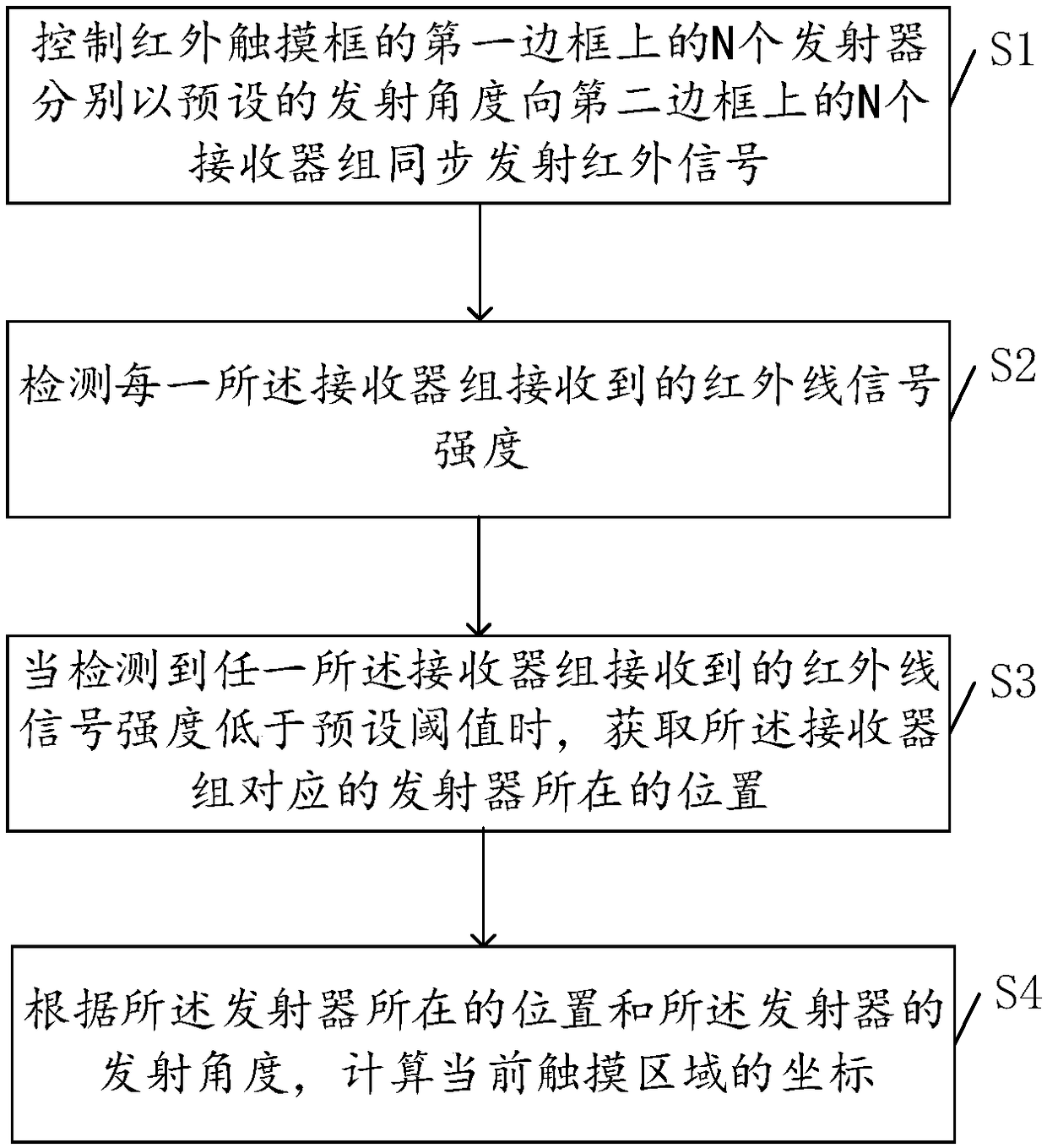
[0043] see figure 2 , is a schematic flow chart of an embodiment of the method for scanning an infrared touch frame provided by the present invention; in the first aspect, the embodiment of the present invention provides a method for scanning an infrared touch frame, which can be executed by an electronic control unit of the infrared touch frame, hereinafter all Taking the controller as the execution subject for illustration, the method for scanning the infrared t...


PUM


Abstract

The invention discloses a scanning method of an infrared touch frame and the infrared touch frame. The method comprises the following steps: controlling N emitters on a first border of the infrared touch frame to synchronously emit infrared signals to N receiver groups on a second border at a preset emitting angle; detecting the intensity of infrared signals received by each receiver group; obtaining a position of a emitter corresponding to a receiver group when that the intensity of the infrared signals received by any receiver group is lower than a preset threshold value is detected; calculating the coordinate of a current touch area according to the position of the emitter and the emitting angle of the emitter. The method realizes the fact of shortening the scanning period of the infrared touch frame, and improves the scanning speed for scanning a whole frame of the infrared touch frame.

Description

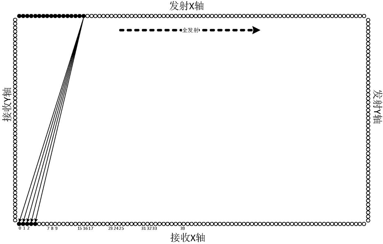
technical field [0001] The invention relates to the technical field of touch screens, in particular to a method for scanning an infrared touch frame and an infrared touch frame. Background technique [0002] The infrared touch screen is composed of infrared emitting and receiving sensing elements installed on the outer frame of the touch screen. An infrared detection network is formed on the surface of the screen. Objects (such as fingers) that are touched can change the infrared rays of the contacts, and then through photoelectric conversion processing Get the coordinate position of the touch to realize the response of the touch operation. [0003] Such as figure 1 As shown, in the prior art, infrared emitters and infrared receivers are closely arranged on the frame of the touch screen. When the infrared touch scanning frame touches and scans the touch screen, the unilateral time-sharing serial scanning method is generally adopted, that is, the infrared sensor is controlle...

Claims


Application Information

Patent Timeline
IPC IPC(8): G06F3/042
CPCG06F3/0428
Inventor 麦金成
Owner GUANGZHOU HUAXIN ELECTRONICS TECH
Learn More