A reaction cavity

A reaction chamber and cavity technology, applied in the field of reaction chambers, can solve the problems of radio frequency leakage and annihilation, and achieve the effect of avoiding radio frequency leakage

Active Publication Date: 2018-09-14
BEIJING NAURA MICROELECTRONICS EQUIP CO LTD
View PDF15 Cites 2 Cited by
  • Summary
  • Abstract
  • Description
  • Claims
  • Application Information

AI Technical Summary

Problems solved by technology

[0005] In order to ensure that the backing ring 3 can have a certain elastic deformation when the backing ring 3 is fixed, the depth of the annular portion 32, that is, the depth of the screen hole should not be too large, but the current sieve hole depth cannot effectively reduce the plasma passing through the sieve hole. Obliterated on the surface of the mesh, which easily leads to radio frequency leakage

Method used


Image

  • A reaction cavity
  • A reaction cavity
  • A reaction cavity

Examples


Embodiment Construction

[0044] In order to enable those skilled in the art to better understand the technical solution of the present invention, the reaction chamber provided by the present invention will be described in detail below with reference to the accompanying drawings.

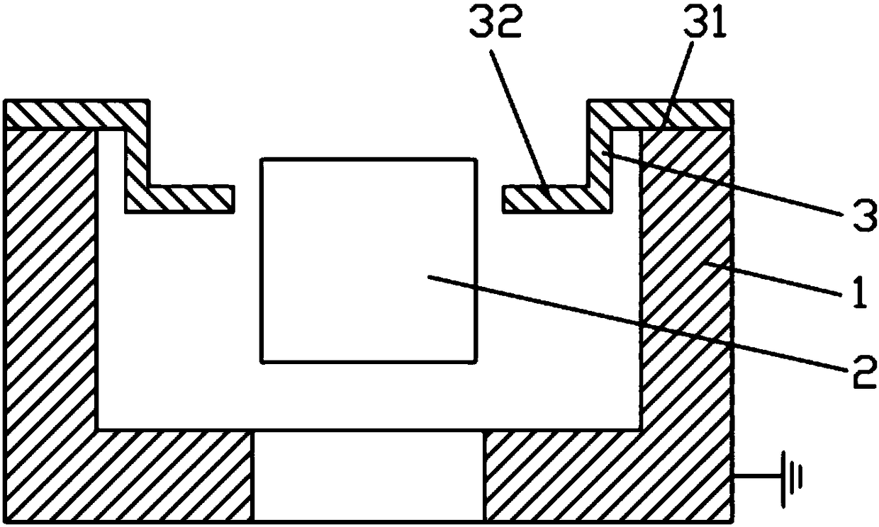
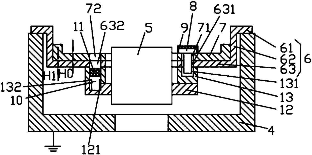
[0045] Please also refer to Figure 2 ~ Figure 6 , the reaction chamber includes a grounded cavity 4, and a lower electrode 5 and a lining assembly are arranged in the cavity 4, wherein the lower electrode 5 is used to carry a wafer, and by applying a radio frequency voltage, attracting plasma to etch the wafer round. The lower electrode 5 is grounded through the cavity 4 .

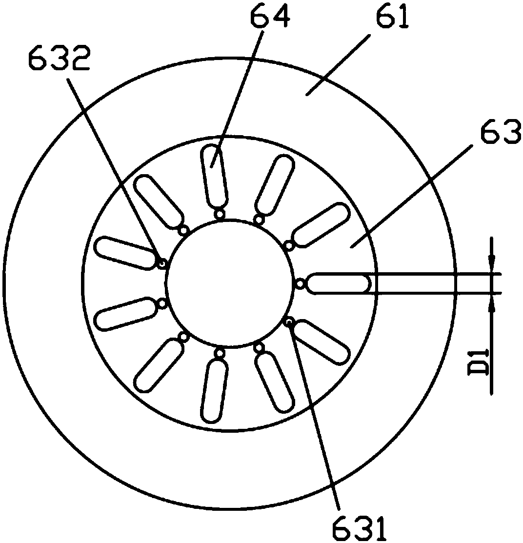
[0046] The lining assembly includes a lining ring 6 , and the lining ring 6 includes a cylinder body 62 , the upper end of the cylinder body 62 is connected to the chamber body 4 and is grounded through the chamber body 4 . Specifically, an annular boss 61 is disposed on the upper end of the barrel 62 , and the lower surface of the annular boss 61 is ...


PUM

PropertyMeasurementUnit
Depthaaaaaaaaaa
Depthaaaaaaaaaa
Short diameteraaaaaaaaaa

Abstract

The invention provides a reaction cavity. The reaction cavity includes an earthed cavity, a lower electrode and a liner assembly are arranged in the cavity. The liner assembly include a lining ring, the lining ring includes a cylinder and an annular part, the upper end of the cylinder is connected with the cavity and is connected to the earth through the cavity; the annular part is horizontally arranged in the lower end of the cylinder and surrounds the surrounding of the lower electrode, and the upper part of the annular part is provided with a plurality of first screen holes arranged in thecircumferential direction. The liner assembly also include an annular backing plate, the annular backing plate is superposed on the annular part, multiple second screen holes are arranged in the annular backing plate, the quantity of the second screen holes is corresponding to the quantity of the first screen holes, and the second screen holes and first screen holes are arranged one-to-one correspondingly. The plasma passing the screen holes can be effectively vanished on the surface of the screen holes, and the leakage of the radio frequency can be avoided.

Description

technical field [0001] The present invention relates to the technical field of semiconductor manufacturing, in particular to a reaction chamber. Background technique [0002] In semiconductor etching equipment, the radio frequency energy provided by the radio frequency power supply is usually transmitted to the reaction chamber, and the special gas (such as argon Ar, helium He, nitrogen N2, hydrogen H2, etc.) in the high vacuum state is ionized to generate Plasma of a large number of active particles such as electrons, ions, excited atoms, molecules and free radicals, and complex interactions between these active particles and the wafer placed in the reaction chamber and exposed to the plasma environment, Various physical and chemical reactions occur on the surface of the wafer material, so that the surface properties of the wafer material change, thereby completing the etching process of the wafer. [0003] When the reaction chamber is ignited and loaded with high RF power...

Claims


Application Information

Patent Timeline
IPC IPC(8): H01L21/67H01J37/32
CPCH01J37/32082H01J37/32431H01L21/67011H01J2237/334
Inventor 聂淼韦刚郭士选
Owner BEIJING NAURA MICROELECTRONICS EQUIP CO LTD
Why Eureka
Try Eureka