
Anaesthetic mask cleaning device for anesthesiology department

A technology for anesthesia masks and cleaning devices, which is applied to liquid cleaning methods, water supply devices, cleaning methods and utensils, which can solve the problems of high labor intensity, low work efficiency, secondary damage to patients, etc., and improve work efficiency , Reduce labor intensity and avoid secondary damage

Inactive Publication Date: 2018-09-18
王克胜
View PDF8 Cites 10 Cited by
  • Summary
  • Abstract
  • Description
  • Claims
  • Application Information

AI Technical Summary

Problems solved by technology

[0002] Among the current medical methods, anesthesia is one of the most common methods. When general anesthesia is performed on patients, an anesthesia mask is needed at this time. In the initial stage of general anesthesia, the anesthesia mask is connected to the anesthesia circuit. Oxygen and volatile anesthetic gas are delivered. When the patient inhales a sufficient amount of anesthetic gas and enters the "sleep" state during the maintenance period of anesthesia, the mask will be removed, and the anesthesiologist will perform tracheal intubation or insert a laryngeal mask on the patient to establish Artificial airway, reusable anesthesia mask, during the process of reusing the anesthesia mask, the anesthesia mask will be cleaned, otherwise it will affect the health of the patient and the progress of the operation. Therefore, the demand for cleaning equipment for the anesthesia mask is increasing, but The current anesthesia masks are manually disinfected when cleaning, the work efficiency is low, and the labor intensity is high. During the cleaning process, most medical staff cannot efficiently process the anesthesia masks, which may affect the operation. Anesthesia masks can cause secondary damage to patients with weak resistance

Method used

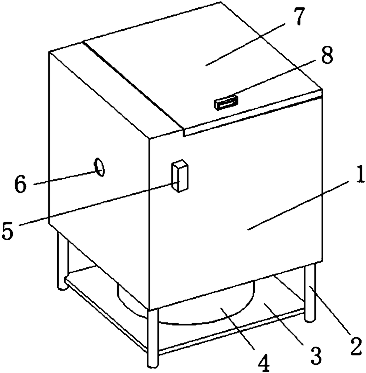
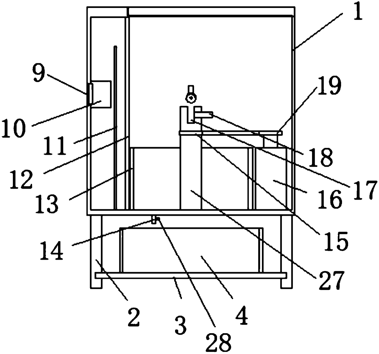
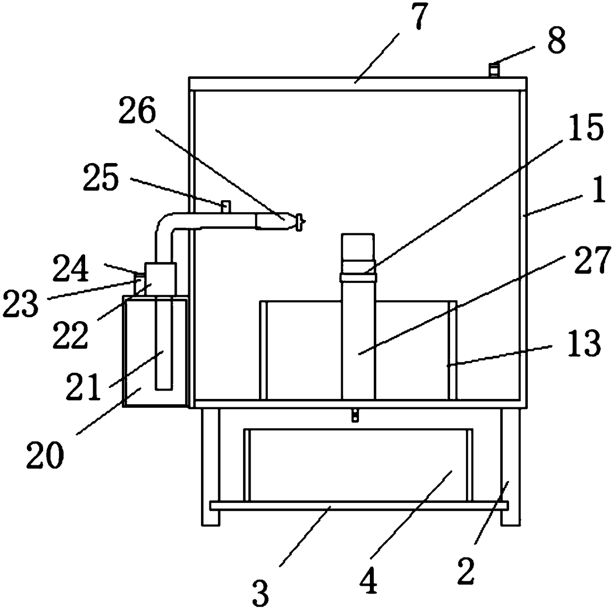

Image

  • Anaesthetic mask cleaning device for anesthesiology department
  • Anaesthetic mask cleaning device for anesthesiology department
  • Anaesthetic mask cleaning device for anesthesiology department

Examples


Embodiment Construction

[0014] The following will clearly and completely describe the technical solutions in the embodiments of the present invention with reference to the accompanying drawings in the embodiments of the present invention. Obviously, the described embodiments are only some, not all, embodiments of the present invention. Based on the embodiments of the present invention, all other embodiments obtained by persons of ordinary skill in the art without making creative efforts belong to the protection scope of the present invention.

[0015] see Figure 1-3 , the present invention provides a technical solution: an anesthesia mask cleaning device for anesthesiology, including a disinfection box 1, an annular waterproof groove 13 is provided on the inner bottom side of the disinfection box 1, and the disinfectant is concentrated, and the center bottom of the inner center of the annular waterproof groove 13 Side is provided with rotating shaft 27 through bearing, and the side of rotating shaft...


PUM


Abstract

The invention discloses an anaesthetic mask cleaning device for the anesthesiology department. The anaesthetic mask cleaning device for the anesthesiology department comprises a disinfectant tank, wherein an annular waterproof groove is formed in the bottom side of the inner part of the disinfectant tank; a rotary shaft is arranged on the bottom side of the center of the inner part of the annularwaterproof groove through a bearing; a first belt pulley is arranged on the side surface of the rotary shaft; a groove is formed in the upper surface of the rotary shaft; a fixed filament is arrangedon the right side of the groove and extends to the outer part of the rotary shaft; an electromotor is arranged on the bottom part of the right side of the disinfectant tank; a second belt pulley is arranged on an output shaft of the electromotor and is connected with the first belt pulley through a belt; and a protecting net is arranged at a position, on the bottom side of the disinfectant tank, on the left side of the annular waterproof groove. The working efficiency is improved, the labor intensity is reduced, and meanwhile, the anaesthetic mask can be disinfected and dried at high temperature, so that a disinfectant effect of the anaesthetic mask is further improved, and patients are prevented from being hurt secondarily.

Description

technical field [0001] The invention relates to the technical field of mask cleaning devices, in particular to an anesthesia mask cleaning device for anesthesia department. Background technique [0002] Among the current medical methods, anesthesia is one of the most common methods. When general anesthesia is performed on patients, an anesthesia mask is needed at this time. In the initial stage of general anesthesia, the anesthesia mask is connected to the anesthesia circuit. Oxygen and volatile anesthetic gas are delivered. When the patient inhales a sufficient amount of anesthetic gas and enters the "sleep" state during the maintenance period of anesthesia, the mask will be removed, and the anesthesiologist will perform tracheal intubation or insert a laryngeal mask on the patient to establish Artificial airway, reusable anesthesia mask, during the process of reusing the anesthesia mask, the anesthesia mask will be cleaned, otherwise it will affect the health of the patien...

Claims


Application Information

Patent Timeline
IPC IPC(8): B08B3/02F26B21/00A61L2/18A61L2/06A61L2/26
CPCA61L2/06A61L2/18A61L2/26A61L2202/15A61L2202/17A61L2202/24B08B3/022F26B21/001
Inventor 王克胜王纪红
Owner 王克胜
Learn More