Automatic spot welding device for metal machining

A technology for automatic spot welding and metal processing

Inactive Publication Date: 2018-09-18
刘道灵
View PDF6 Cites 8 Cited by
  • Summary
  • Abstract
  • Description
  • Claims
  • Application Information

AI Technical Summary

Problems solved by technology

[0002] Metal processing is a series of process treatments for metal. In the process of metal processing, some workpieces need to be spot welded. Spot welding is to weld individual points on the contact surface of the weldment at the joint. The existing spot welding device The structure is rigid, and the material cannot be automatically pushed directly under the briquetting block during use. Manual operation is required, which is time-consuming and labor-intensive, which increases labor intensity. The spot welding position is often inaccurate due to inaccurate feeding position, which reduces the accuracy of the spot welding device. Inability to make it possible to flexibly adjust the distance between the welding heads according to the position of the spot welding required, and unable to make the structure flexible and adjustable, reducing the practicability of the spot welding device and reducing production efficiency

Method used


Image

  • Automatic spot welding device for metal machining
  • Automatic spot welding device for metal machining
  • Automatic spot welding device for metal machining

Examples


Embodiment Construction

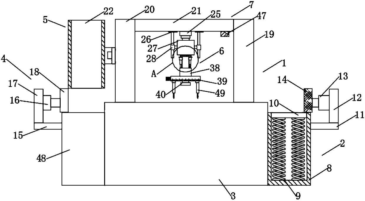
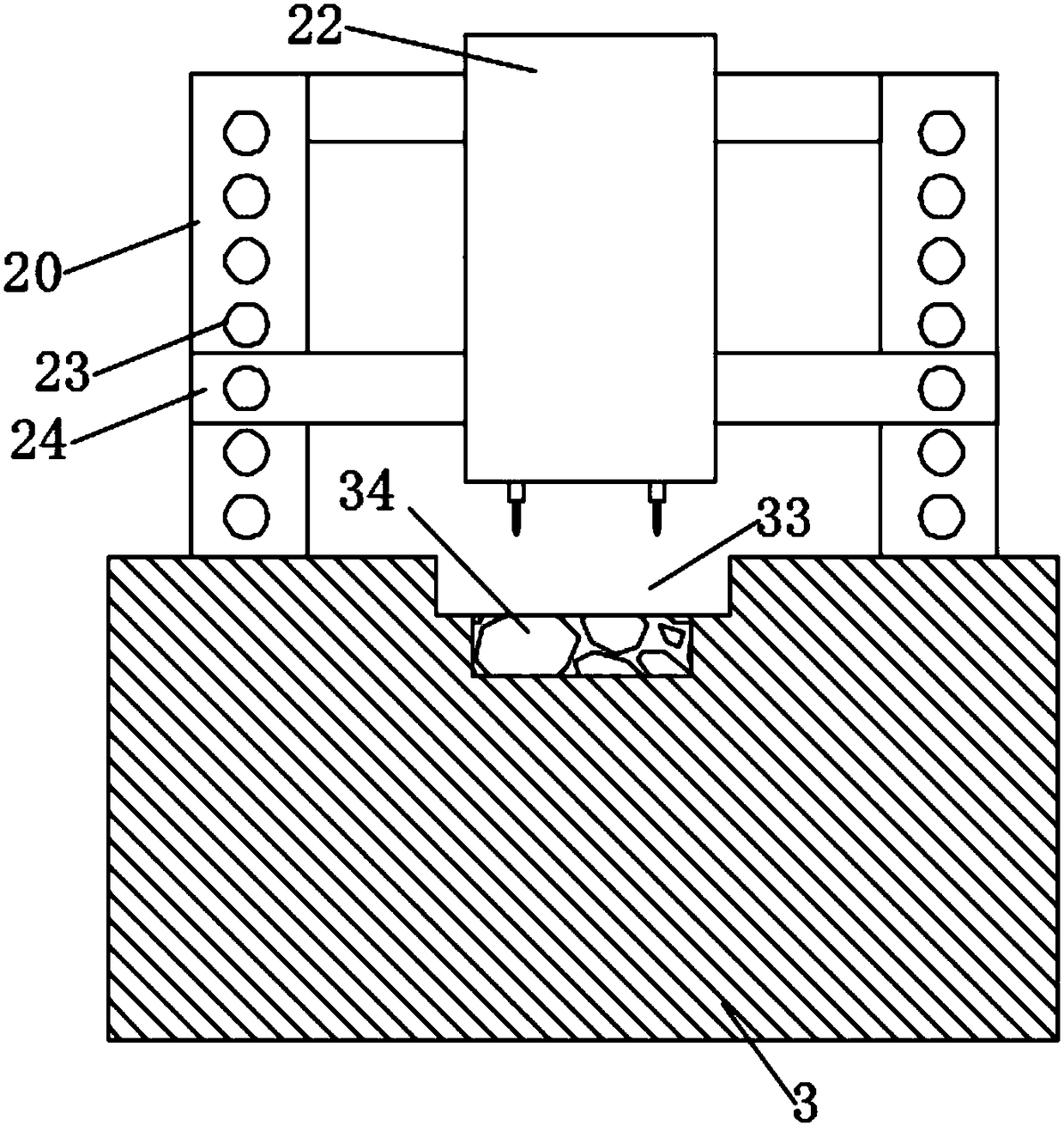
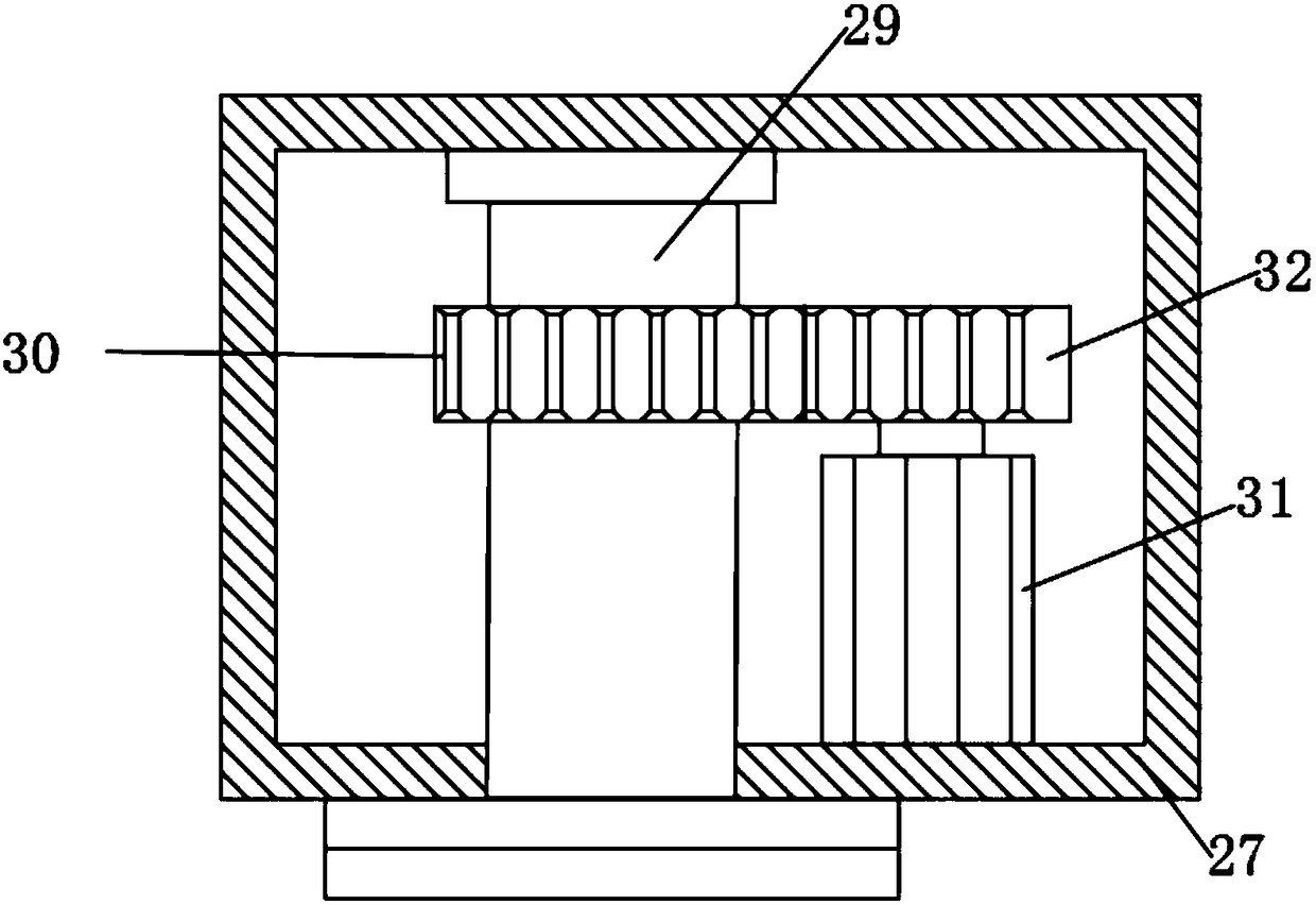
[0021] like Figure 1-5 As shown, the present embodiment adopts the following technical solutions: an automatic spot welding device for metal processing, comprising a spot welding device body 1, and the spot welding device body 1 is composed of a receiving mechanism 2, a workbench 3, a feeding mechanism 4, The material storage mechanism 5, the spot welding mechanism 6 and the support mechanism 7 are composed, one end of the workbench 3 is fixedly connected with the material receiving mechanism 2, and the other end of the workbench 3 is fixedly connected with the feeding mechanism 4 relative to the material receiving mechanism 2 , the top of the workbench 3 is fixedly connected with a support mechanism 7, and one end of the support mechanism 7 close to the feeding mechanism 4 is fixedly connected with a material storage mechanism 5, and the bottom of the support mechanism 7 is fixedly connected with a spot welding mechanism 6, so The support mechanism 7 is composed of a first p...


PUM


Abstract

The invention discloses an automatic spot welding device for metal machining. The automatic spot welding device comprises a spot welding device body, the spot welding device body consists of a material receiving mechanism, a worktable, a feeding mechanism, a material storage mechanism, a spot welding mechanism and a supporting mechanism, wherein one end of the worktable is fixedly connected with the material receiving mechanism, the other end which is relatively to the material receiving mechanism of the worktable is fixedly connected with the feeding mechanism. According to the device, the structure is compact, the feeding usage of the metal machining is facilitated, through the arrangement of the feeding mechanism, a material is pushed to the right lower part of a pressing block througha feeding hydraulic cylinder during use, so that manual operation is not needed, the device is simple and convenient, the labor intensity is reduced, the inaccurate spot welding position caused by inaccurate feeding position is avoided, and the accuracy of the spot welding device is improved; and through the arrangement of a rotating box and a distance adjusting motor, the distance between weldingheads can be flexibly adjusted according to the position where the spot welding is needed by the spot welding device, so that the structure of the spot welding device is flexible and adjustable, thepracticability of the spot welding device is improved, and the production efficiency is improved.

Description

Technical field: [0001] The invention relates to the technical field of metal processing, in particular to an automatic spot welding device for metal processing. Background technique: [0002] Metal processing is a series of process treatments for metal. In the process of metal processing, some workpieces need to be spot welded. Spot welding is to weld individual points on the contact surface of the weldment at the joint. The existing spot welding device The structure is rigid, and the material cannot be automatically pushed directly under the briquetting block during use. Manual operation is required, which is time-consuming and labor-intensive, which increases labor intensity. The spot welding position is often inaccurate due to inaccurate feeding position, which reduces the accuracy of the spot welding device. It is impossible to make it flexible to adjust the distance between the welding heads according to the position of spot welding, and it is impossible to make its st...

Claims


Application Information

Patent Timeline
Patent Type & Authority Applications(China)
IPC IPC(8): B23K37/02B23K37/047
CPCB23K37/0252B23K37/047
Inventor 刘道灵
Owner 刘道灵
Why Eureka
Try Eureka