

Waste cotton wool compressor
A technology of compressors and cotton wool, which is applied in the direction of presses, manufacturing tools, etc., can solve the problems of low density of waste cotton wool, large space occupation, high production cost, etc., and achieve the effect of saving manpower and material resources and improving compression efficiency
- Summary
- Abstract
- Description
- Claims
- Application Information
AI Technical Summary
Problems solved by technology
Method used
Image

Examples
Embodiment Construction
[0017] Through the description of the embodiments below, the specific implementation of the present invention includes the shape, structure, mutual position and connection relationship between the various parts, the function and working principle of each part, the manufacturing process and the operation and use method of the various components involved. etc., to make further detailed descriptions to help those skilled in the art have a more complete, accurate and in-depth understanding of the inventive concepts and technical solutions of the present invention.
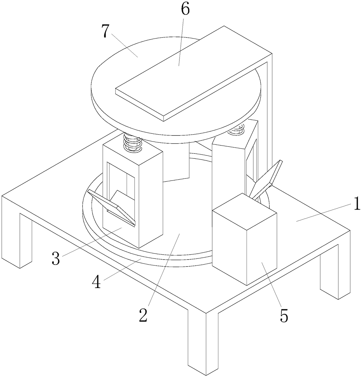
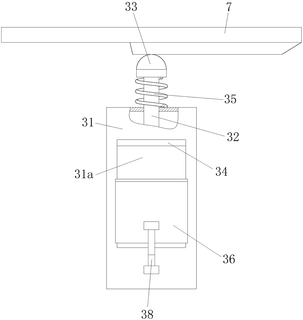
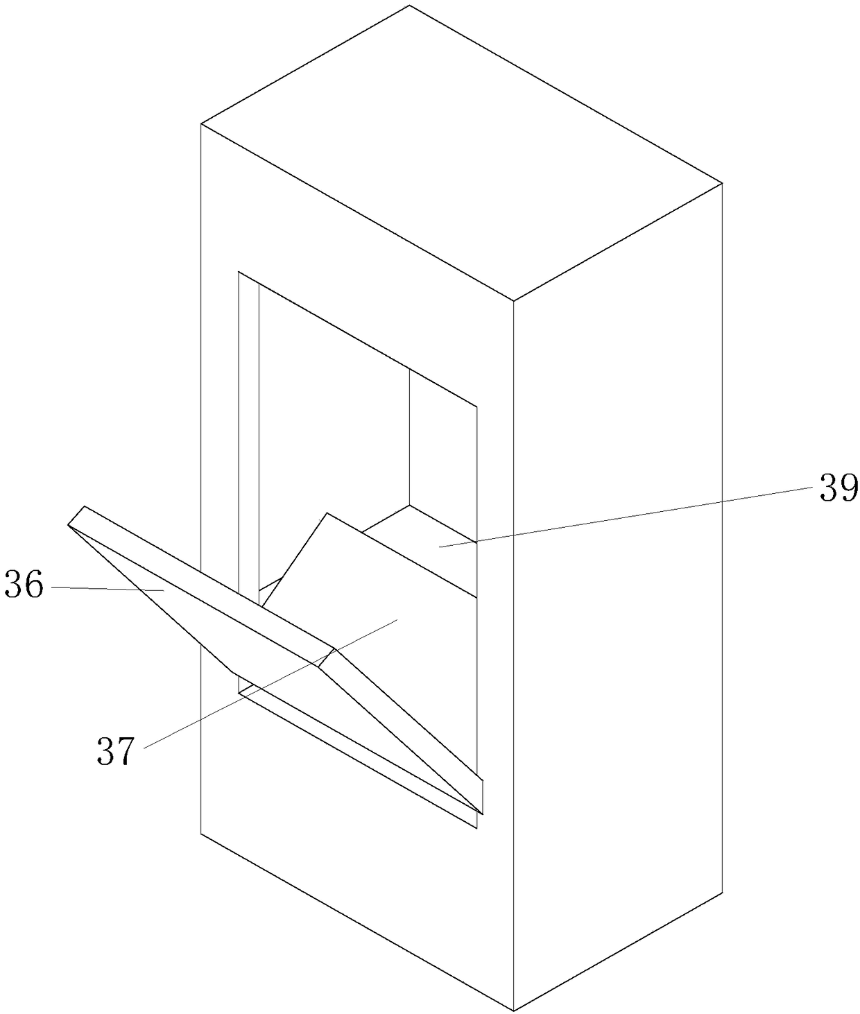
[0018] A waste wadding compressor, comprising a workbench 1, a turntable 2 is installed on the workbench 1 through bearing connection, several groups of compression units 3 are installed on the turntable 2, and the outer wall of the turntable 2 is connected by bolts The ring gear 4 is installed in the way, and the drive assembly 5 is installed on the right part of the workbench 1. The drive assembly 5 includes a drive m...
PUM
 Abstract
Description
Claims
Application Information