Test paper tidying and storing device
A storage device and test paper technology, applied in the direction of thin material processing, transportation and packaging, sending objects, etc., can solve the problems of inability to dry, inability to purify the smell of paint, etc., to achieve the effect of easy collection and organization, and improve picture quality
- Summary
- Abstract
- Description
- Claims
- Application Information
AI Technical Summary
Problems solved by technology
Method used
Image

Examples
Embodiment Construction
[0018] Below, the technical solution of the present invention will be described in detail through specific examples.
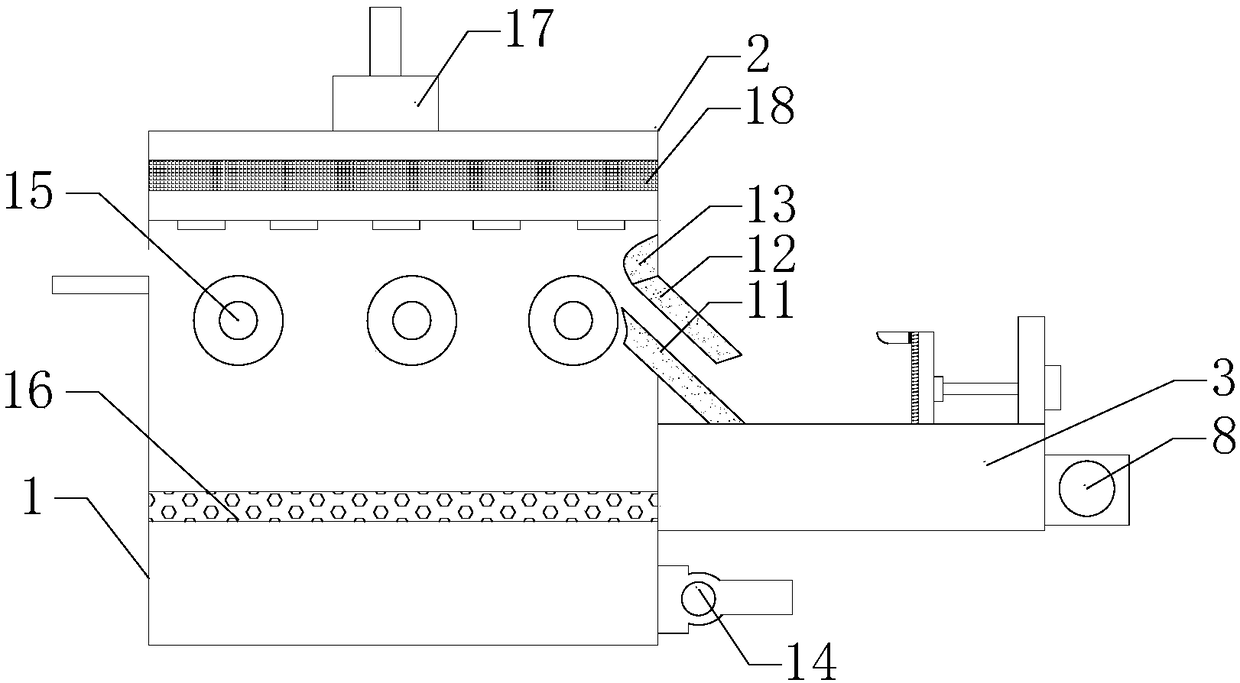
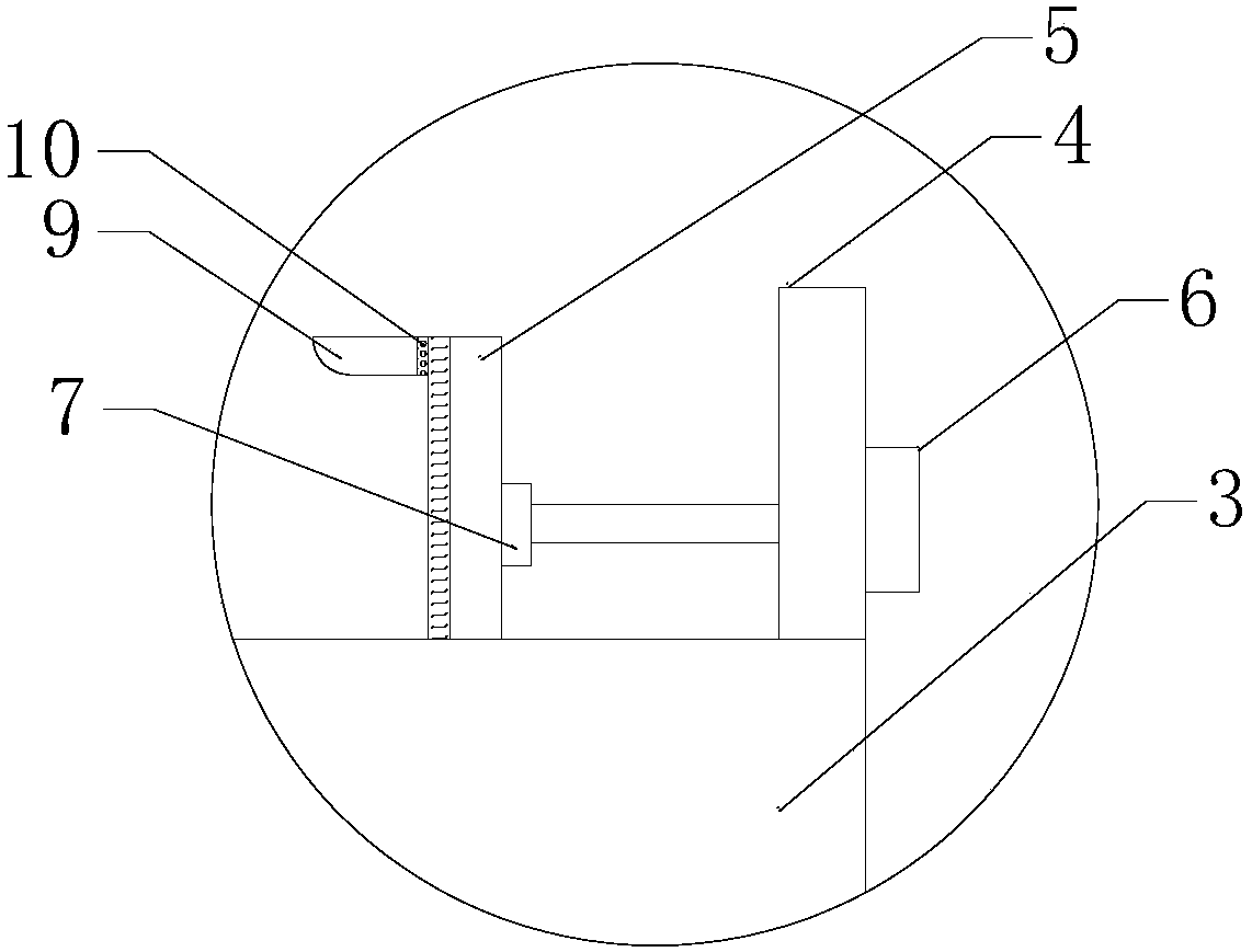
[0019] Such as Figure 1-2 as shown, figure 1 It is a structural schematic diagram of a test paper arrangement and storage device proposed by the present invention; figure 2 It is a schematic diagram of the structure of the supporting plate in a test paper sorting and storing device proposed by the present invention.
[0020] refer to Figure 1-2 , a test paper sorting and storage device proposed by the embodiment of the present invention, comprising: a box body, a first induced draft fan 14, a second induced draft fan 17 and a supporting plate 3, wherein: the box body has a transfer chamber 1 and is located above the transfer chamber 1 and Airflow chamber 2 communicating with transfer chamber 1.
[0021] One side of the transfer chamber 1 is provided with a paper inlet, and the side away from the paper inlet is provided with a paper outlet; inside the tr...
PUM
 Abstract
Description
Claims
Application Information
PatSnap Eureka turns technology decisions into work you can execute. Powered by our Innovation Knowledge Graph, it runs expert workflows across engineering, life sciences, materials and intellectual property. Get your review-ready output in minutes.


